Bandsaw Restoration: Switch Housing
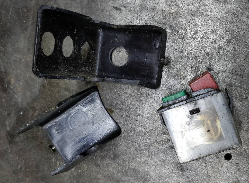 |  |
When I bought the bandsaw in 2011, the housing around the power switch was in two pieces, held together with electrical insulation tape. The switch also looked a bit shabby and has gradually deteriorated over the 8 years I've owned the machine. As I was restoring the rest of the bandsaw, it seemed a good time to do something about the switch and housing. I bought a new switch on Amazon. It isn't specifically designed for the bandsaw but was advertised as a 250 V NVR (no-volt release) switch and the dimensions looked approximately correct.
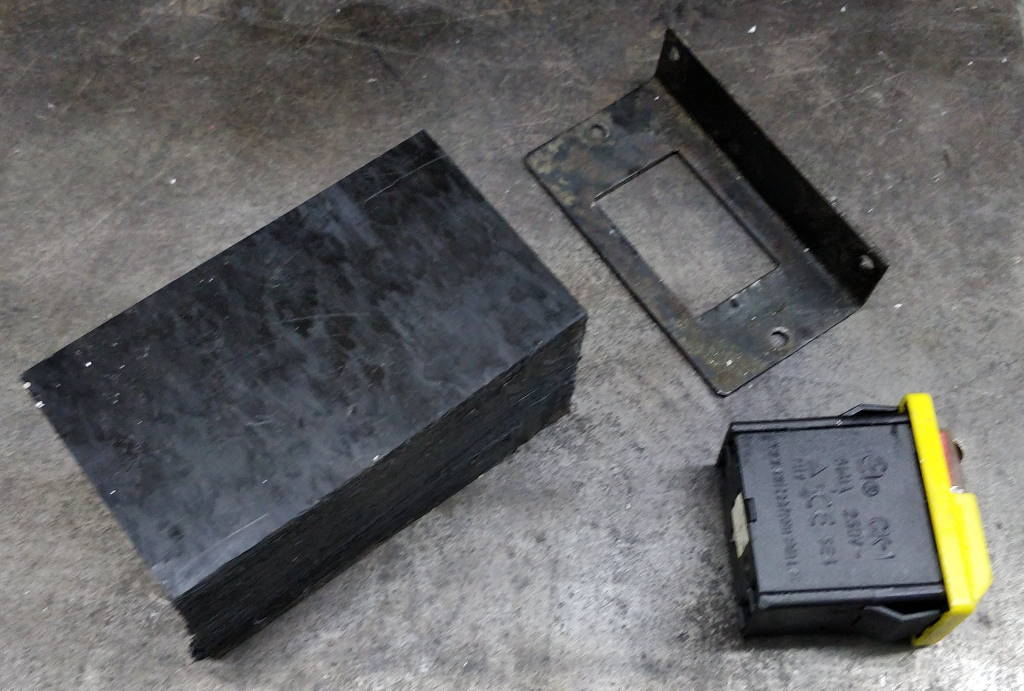 |
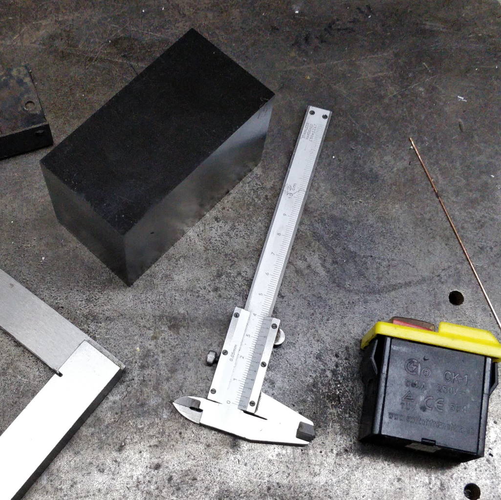
For the housing, I had a large block of black acetal, so I hacksawed off a lump of this of about the right size. The raw material can be seen in this photo along with the switch and the mounting bracket (which I re-painted black after taking this photo).
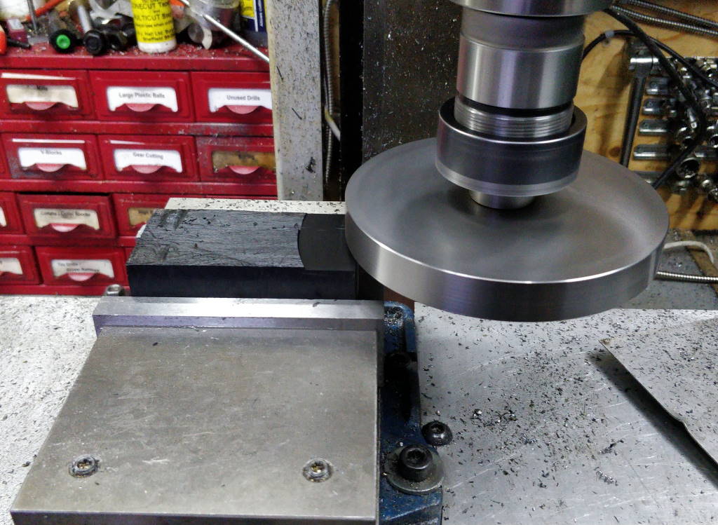 |  |
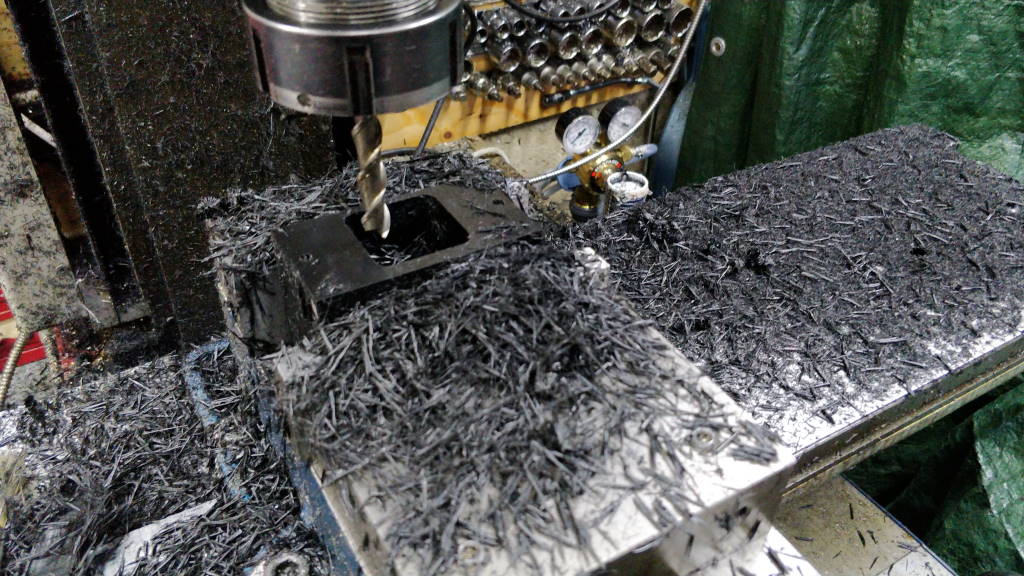
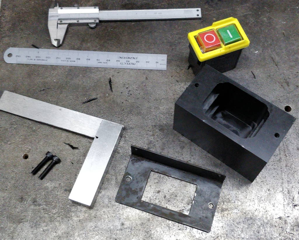
I cleaned up the block with my Flywheel Fly Cutter: the photo on the left shows an "action shot" of one of the face cuts and gives an idea of the lovely finish that can be achieved with a fly cutter. The photo on the right shows the finished result.
 |  |
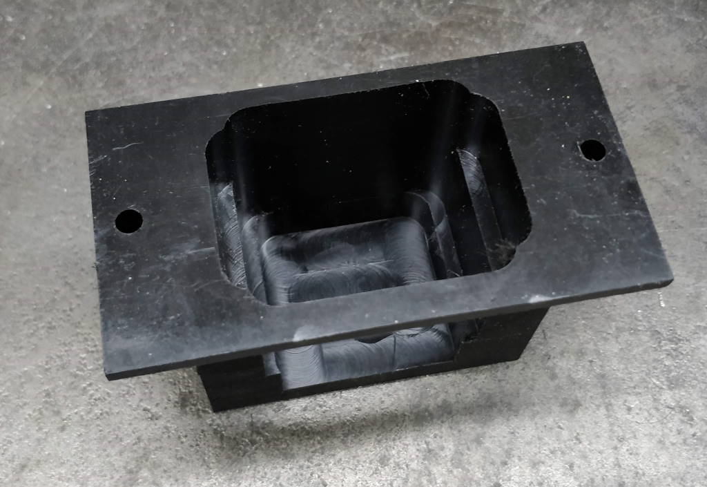
I then used a 10 mm long series two flute uncoated end mill (from Arc Euro Trade) to mill out a pocket for the switch. This also ensured that any surfaces in my workshop that the fly cutter hadn't covered in plastic swarf had their opportunity to be turned black!. The photo on the right shows the block after the pocket had been milled out.
 | 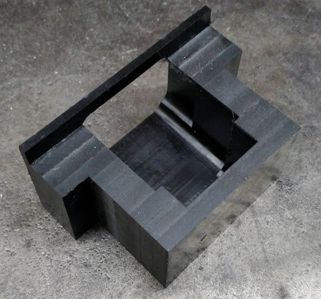 |
I then returned the block to the milling machine and took some more cuts on the rear and side faces. The side faces are milled away so that the body can be mounted with a screw and a nut. I had originally planned to use tapped holes in the acetal, but I changed my mind and went for a screw and nut. The switch housing shouldn't take much of the force of the bandsaw arm coming down onto the switch (as it should be transmitted into the casting via the switch and the mounting plate), but the fact that the original housing had been broken in two made me a little concerned and any vibration resulting from the arm coming down could gradually damage the plastic threads.
The rear face is milled away for two reasons. Firstly there needs to be clearance to the casting as the face that the mounting plate attaches to is set back from the bottom edge of the casting. Secondly, the earth connection is on the body of the casting behind the switch housing and hence the back needs to be open to allow the cable to attach to the casting.
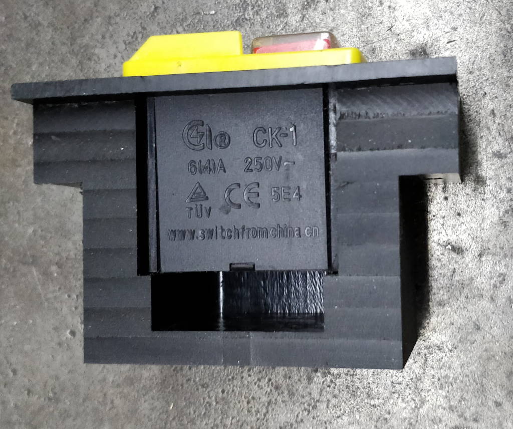 |
This photo shows how the new switch fits within the switch housing. The cable access holes have yet to be made in this photo.
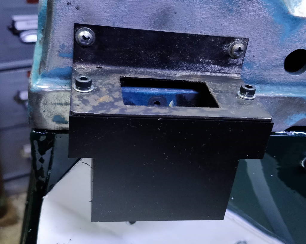 | 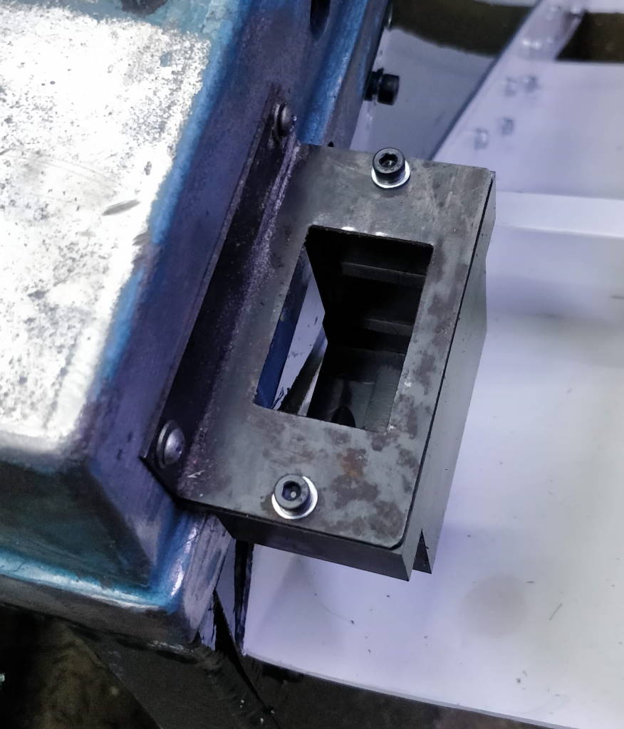 |
These photos show a trial fit and demonstrate how the switch housing fits on the bottom casting.
Machining the Cable Entries
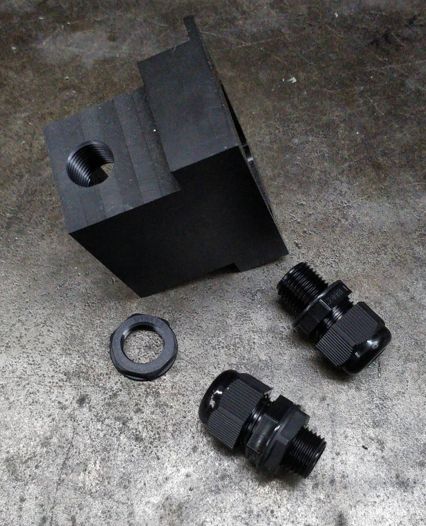 |
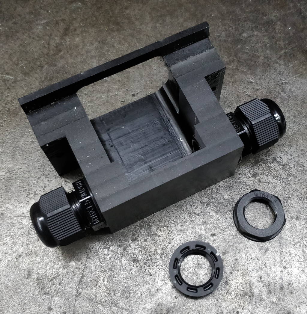
This photo shows one of the holes that was drilled and tapped (M16×1.5) in either side of the switch housing. Next to the switch housing you can see two M16 conduit entries (bought from RS) to be used as strain relief on the power cables.
 | 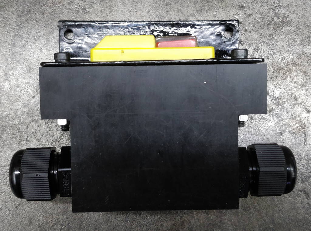 |
These photos show the housing with the conduit entries and (in the right-hand photo) switch fitted. The nuts you can see in the left-hand photo were supplied with the conduit entries but were not required for this use.
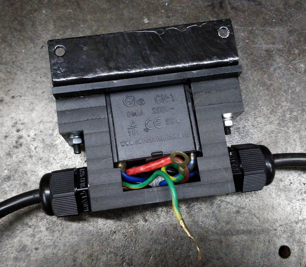 | 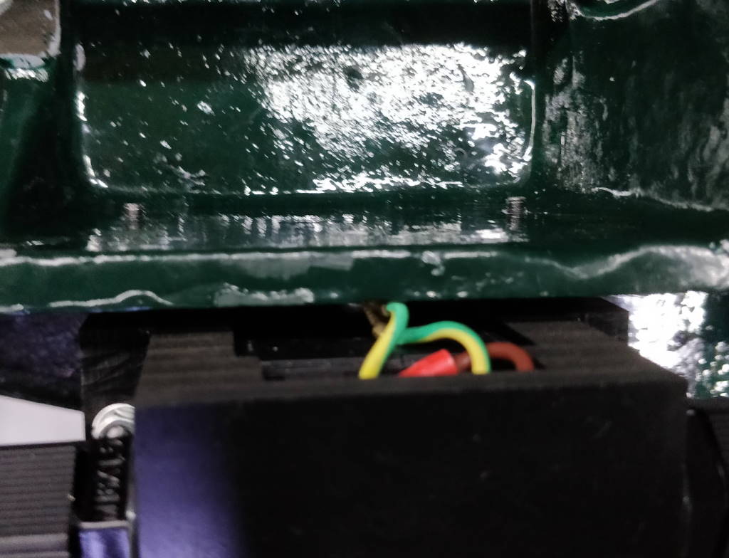 |
These photos show the wiring to and from the switch. The space for the wire is limited, but the cables fit okay without any of the edges of the switch housing rubbing against the wire. The earth cables come out the back of the switch housing and are connected to an earth point on the bottom bandsaw casting.
This website is free, but costs me money to run. If you'd like to support this site, please consider making a small donation or sending me a message to let me know what you liked or found useful.