Bandsaw Restoration: Disassembly
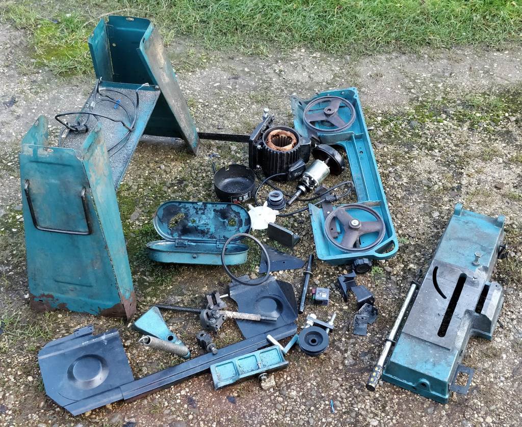 |
This photo shows the parts of the bandsaw after the initial dismantling.
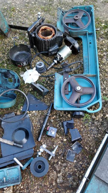 |
This is a close-up of the main parts of the bandsaw. If you look closely you can see the blade guard in two pieces and the switch housing in two pieces. You can also see I've taken the motor apart; even after I'd reshaped the fan housing, it was quite noisy; so I decided to change the bearings as part of this rebuild.
The photo above was taken before I dismantled the upright arm of the bandsaw. This incorporates a worm and wheel gearbox, which was very difficult to take apart. One shaft came out with judicious use of a hammer; the worm shaft was more difficult.
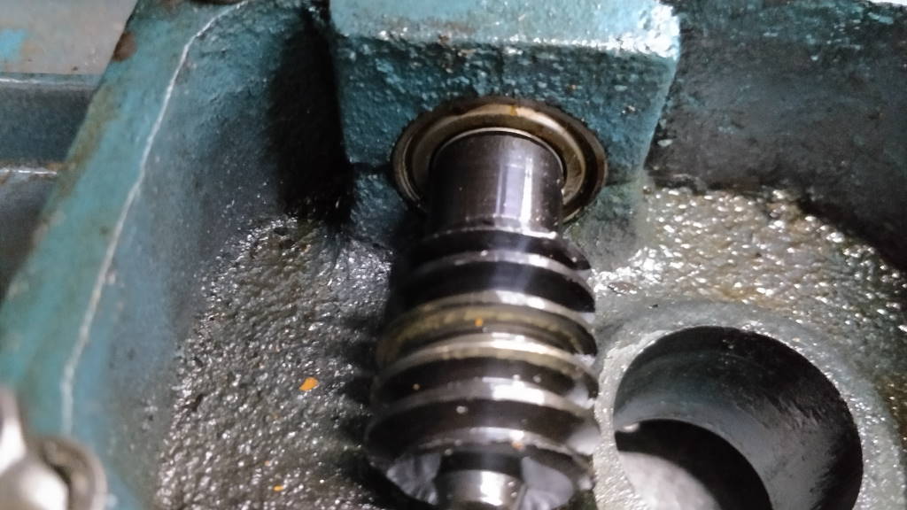 | 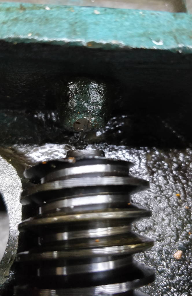 |
These photos show the worm shaft in place after the worm wheel has been removed. I spent a long time trying to figure out how to get this shaft out as there's no obvious place where it can be pushed. I'd wondered about drilling and tapping a hole in the casting (where the boss is that you can see at the end of the worm shaft), but I didn't really want to modify the casting, it would be awkward to reseal and it would be very difficult to hold it in the pillar drill or mill and hence would have to be hand drilled.
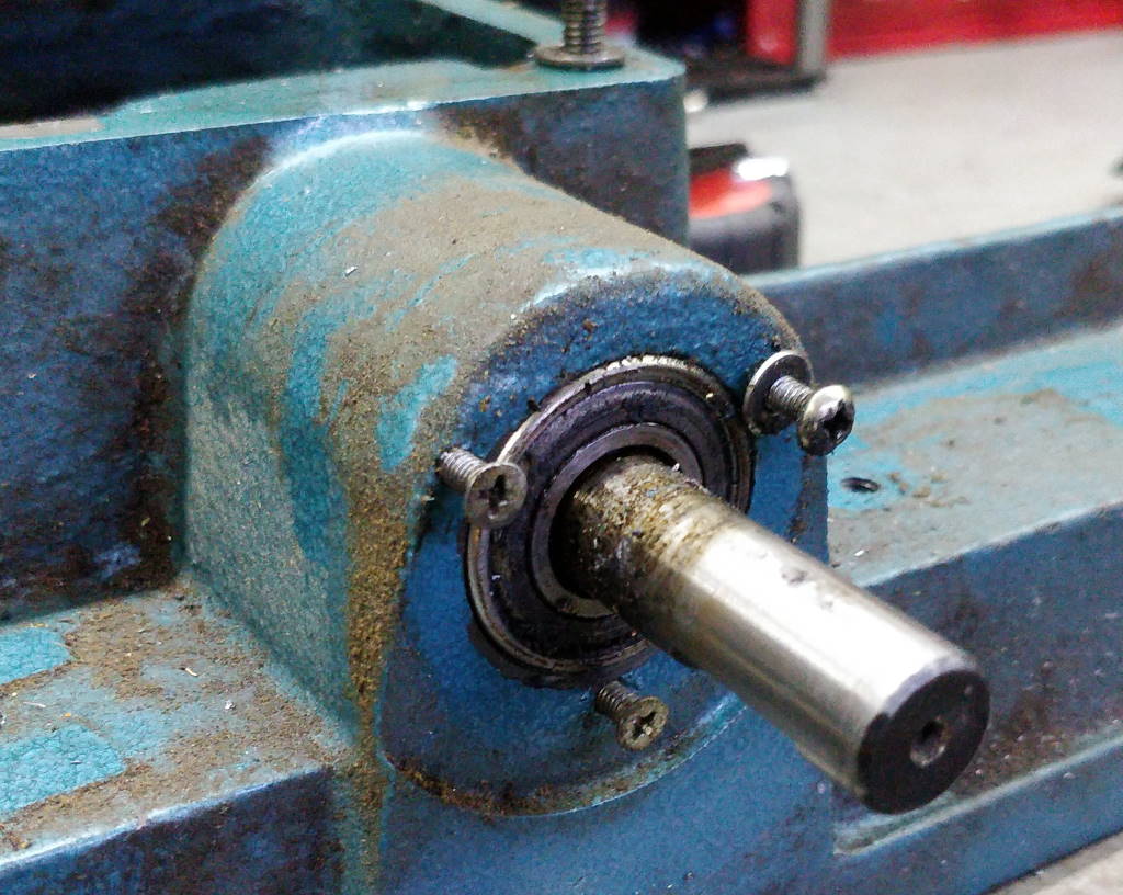 |
This photo shows the end of the worm shaft. There is a plate (which has been removed for this photo) that retains the bearing and stops the shaft working its way out as a result of the worm reaction. The only other thing keeping the shaft in place is the friction from the two bearings and the oil seal.
 |
After asking advice on the excellent MIG Welding forum (which covers a much broader subject area than just MIG welding), I concluded the best option would be a slide hammer that grips the shaft. I already had a full set of ER32 and ER40 collets and the shaft was 15 mm. Since I had some handy 40 mm stock lying around, I decided to make an ER32 slide hammer. As mentioned on the page describing the slide hammer, I don't think the ER system is the ideal choice for a slide hammer as the nut kept working itself loose. However, it worked and I got the shaft out.
 | 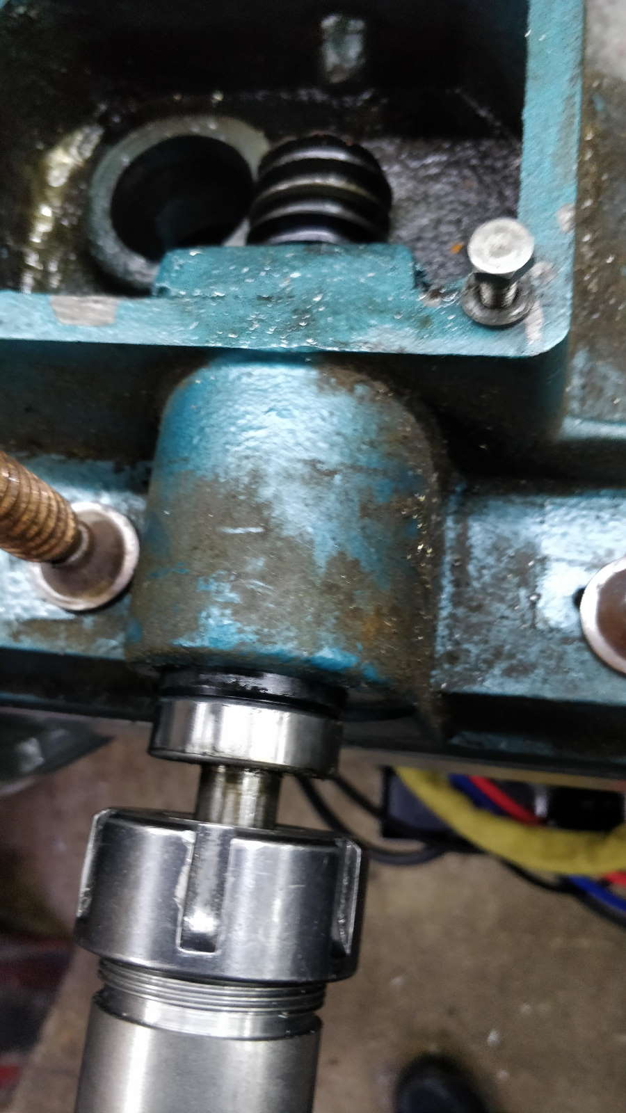 |
These photos show the slide hammer in use. As you can see, the casting was simply held to the bench with a couple of G-Clamps.
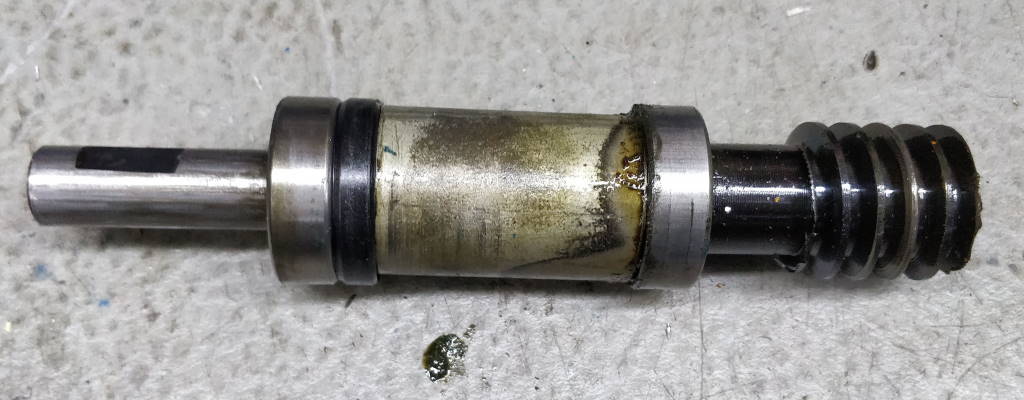 | 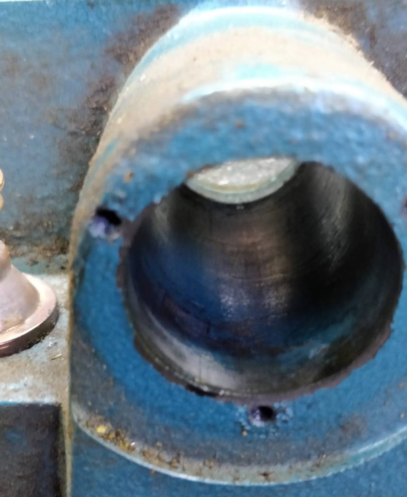 |
These photos show the worm shaft once it had been removed and the bore from whence it came. The yellowy coloured bit between the right-hand bearing and the oil seal is a fairly loose spacer.
This website is free, but costs me money to run. If you'd like to support this site, please consider making a small donation or sending me a message to let me know what you liked or found useful.