Bar Clamps Build Process
16/5/2021
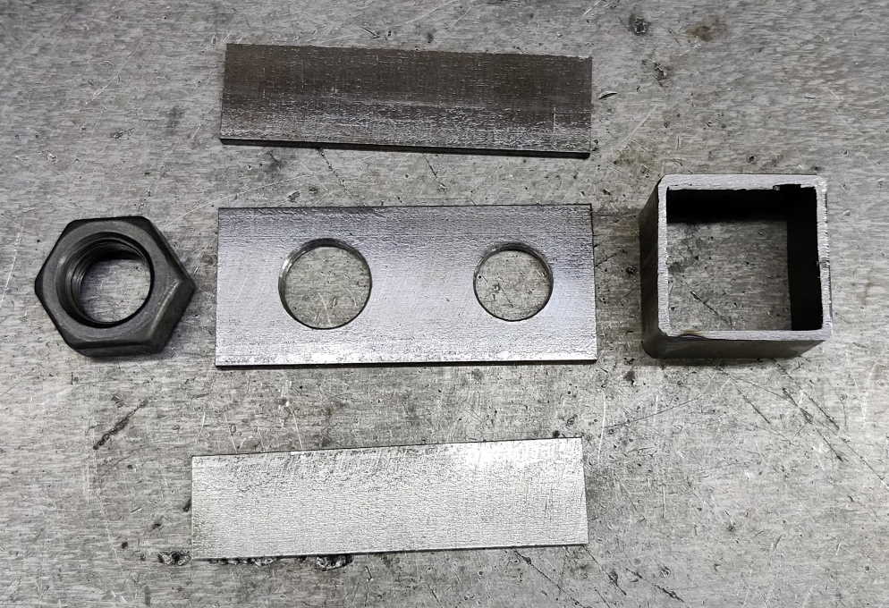 |
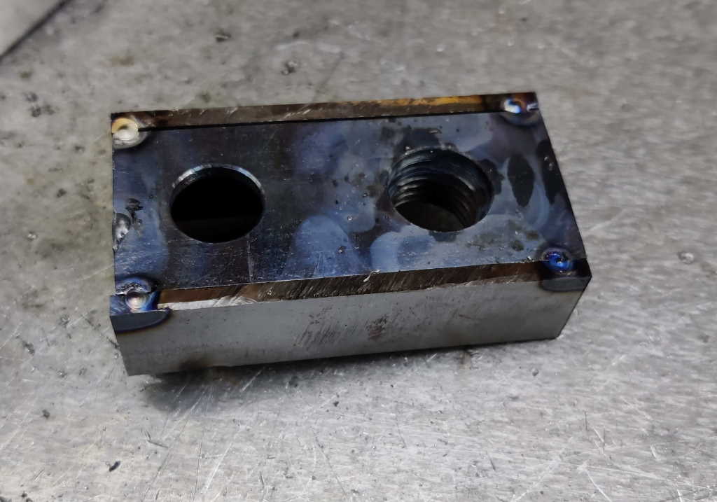
The end plates were next. The holes drilled in the end plate are 16 mm and 14 mm. The smaller hole is the equivalent of the hole in the end cap - a very loose fit for the M12 set screw that holds the end plate in place. The 16 mm hole is a close-ish fit on the the M16 threaded rod for the clamping screw. Ideally this would have been drilled a bit bigger to make sure that the threaded rod easily cleared the hole (as I did on the back plates for the screw jaws), but having a 16 mm hole means that I can use the hole to help align the nut in the right place. If the nut moves slightly during welding and the hole is causing interference with the threaded rod, I can pass a tap through from the nut side and extend the thread into the plate.
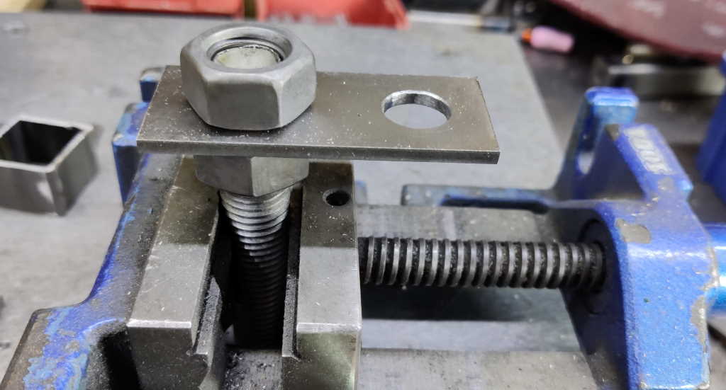 |
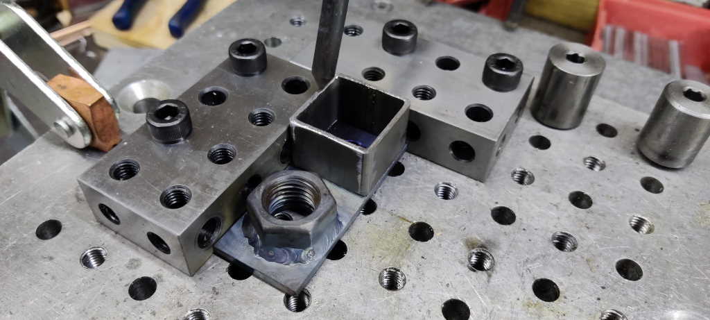
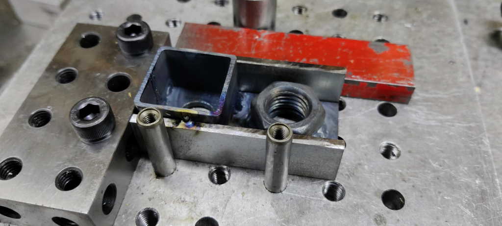
This shows the "jig" I used to position the nuts. It's a bit of threaded rod held in a vice with a nut above and below the plate. The nut above the plate can easily be lined up with the plate for a consistent orientation.
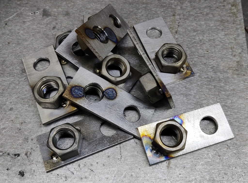 |
I tacked two sides of each nut while it was in the jig, then removed it from the jig.
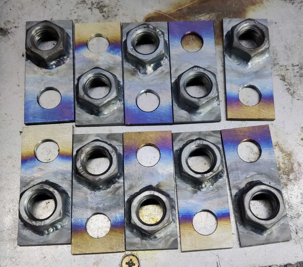 |
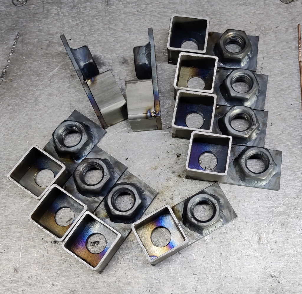
I then welded round all six sides of each nut. This is probably overkill (two sides would have provided plenty of strength), but I was enjoying welding.
 |
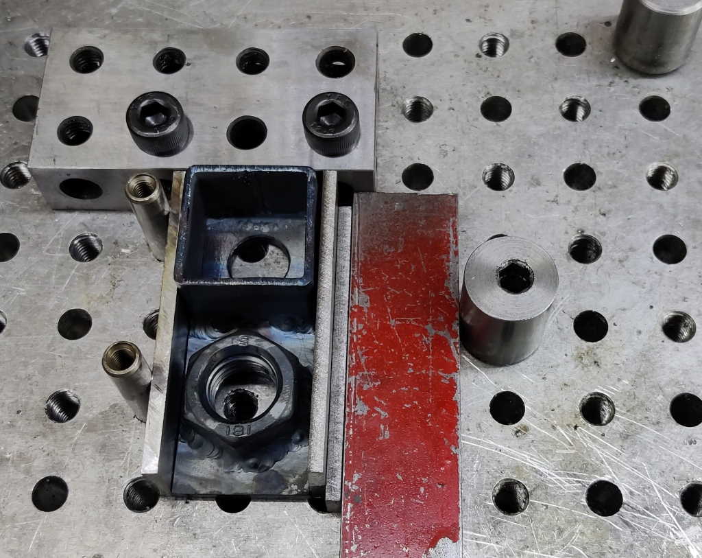
The small piece of 30 mm × 30 mm × 2 mm box section is there to help align the end plate with the long bars while the M12 screw is tightened to hold them in place. It's not really necessary and I partly only added it as it adds some symmetry with respect to the end caps on the other end of the bars. To fit the box section, I used my fixture plate again; this made it very quick to add one tack in the corner.
 |
I then took the piece out of the jig and tacked the other corner. As with most previous operations, I tacked all the parts together in one go and then went back to weld them all.
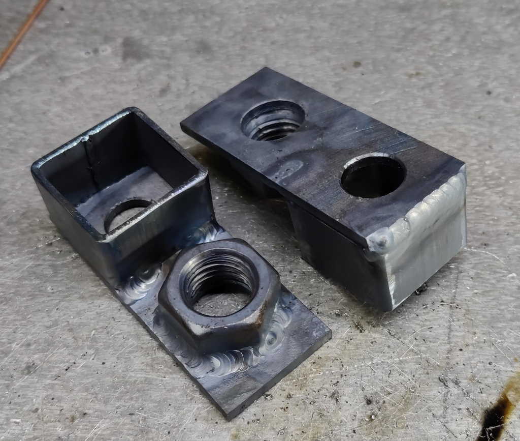 |
As the box section isn't structural and to save me a lot of work grinding the sides down, I just welded the box section on two sides (and one of those sides was only partly welded due to access behind the nut).
 |
The side plates were attached using the fixture plate again. This time I swapped one of the 20–40–80 blocks for a couple of 8 mm dowel pins to give better access. The eccentric screw made clamping each one in place very quick.
 |
I tacked the two sides in place at the top while the end plates were in the jig.
 |
I then tacked the rear in a few places to hold it firmly.
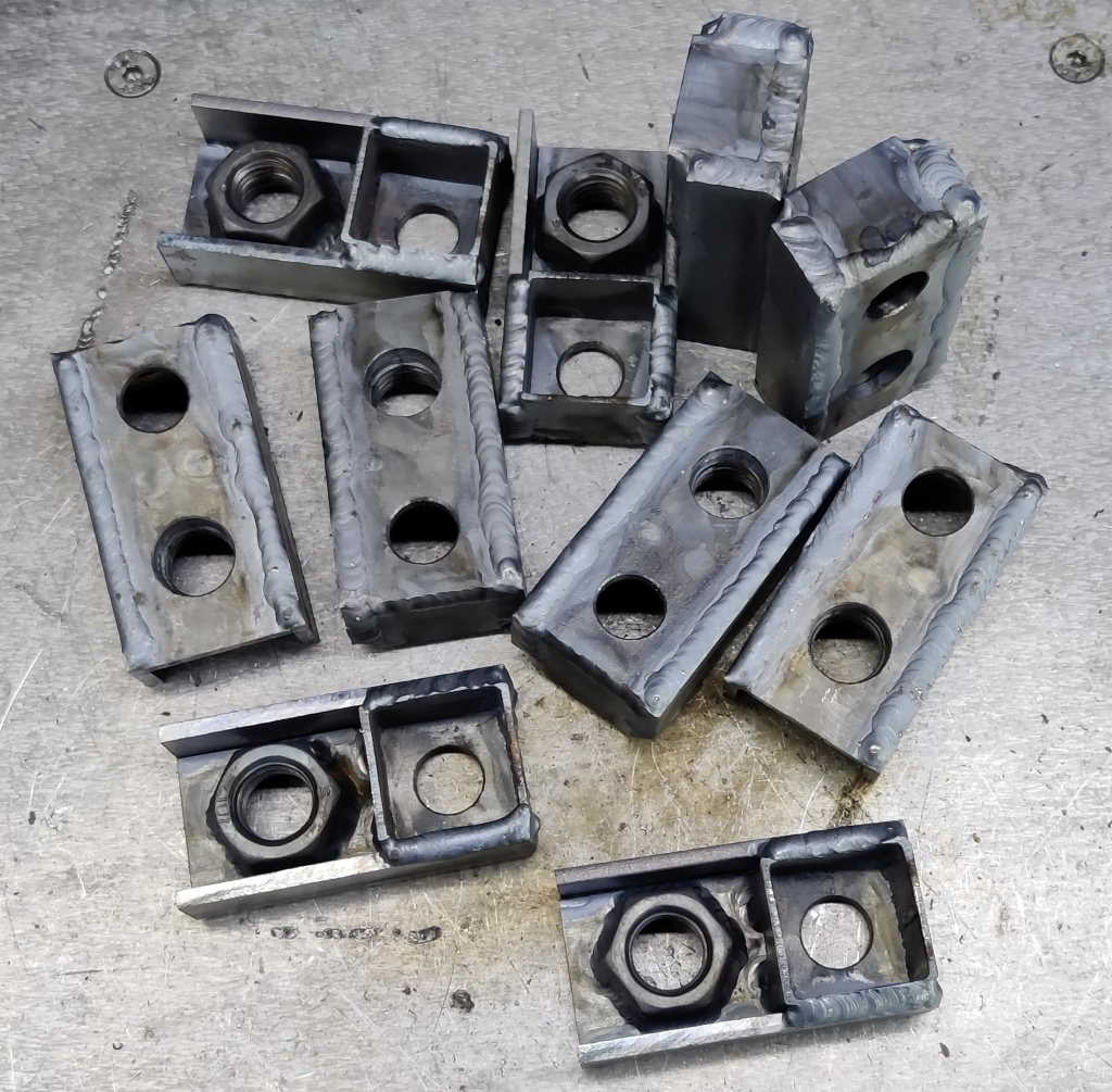 |
Finally, I welded round three sides of each side plate. I'll probably round all the edges and corners off with an angle grinder once the weather improves (I prefer to do angle grinding outside), but otherwise these parts are complete and ready for painting.
The only remaining welding to do on this project (unless I've forgotten something!) is to attach the second M16 split nut to its threaded rod to hold the threaded rod in place on the screw jaw.
Page Navigation:
| First (#1) | Previous (#22) | Next (#24) | Last (#32) |
This website is free, but costs me money to run. If you'd like to support this site, please consider making a small donation or sending me a message to let me know what you liked or found useful.