Bar Clamps Build Process
9/5/2021
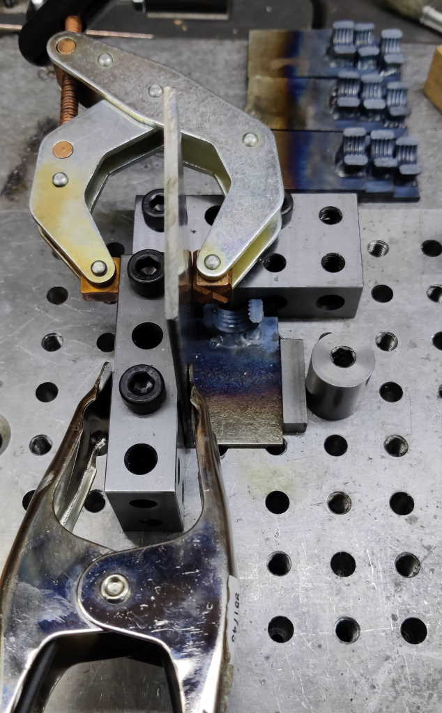 |  |
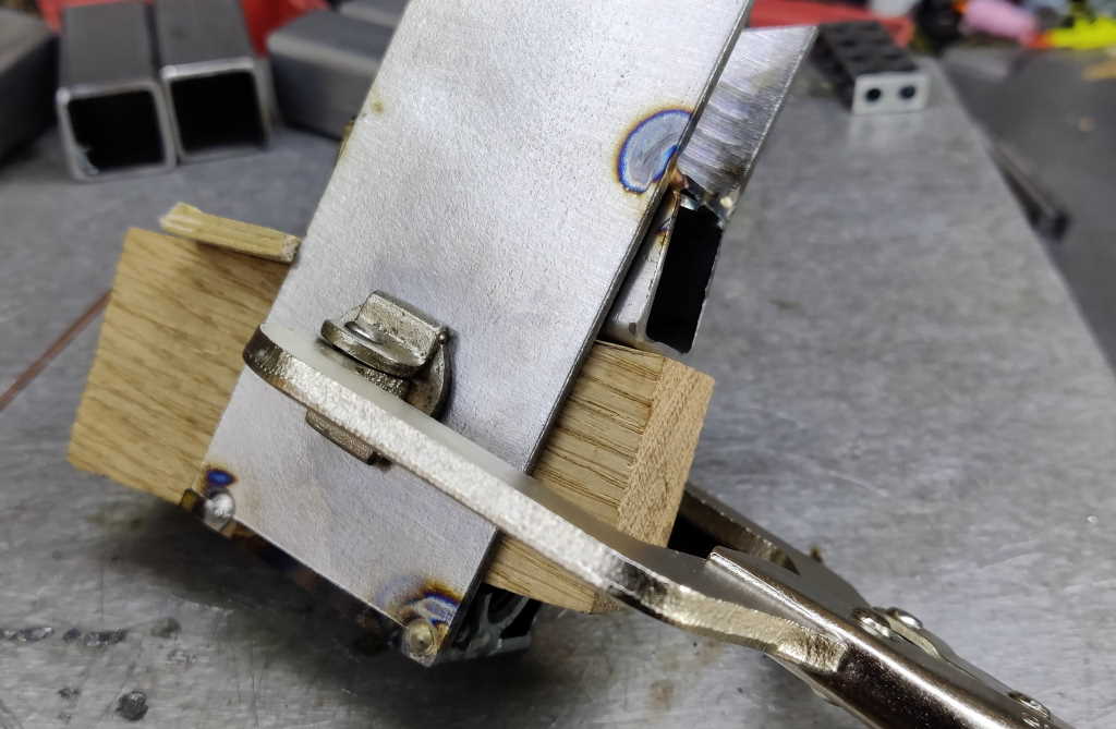
This afternoon I started work on tack welding the frames together. It's amazing how long everything takes when you have to multiply each job by 10! The photos above show the jig I used to attach the first side to the base of the sliding jaw. It's based on an aluminium fixture plate I made a few years ago. The fixture plate has holes (alternately reamed 8 mm and tapped M8) on a 20 mm grid, so I attached a couple of 20-40-80 blocks to use as reference edges. An eccentric screw clamps the base into place and then a spring clamp holds the side of the frame in place to make it easier to attach the cantilever clamp to hold it more firmly.
 |
For now I just did a couple of tack welds along the bottom edge to join the pieces together.
 |  |
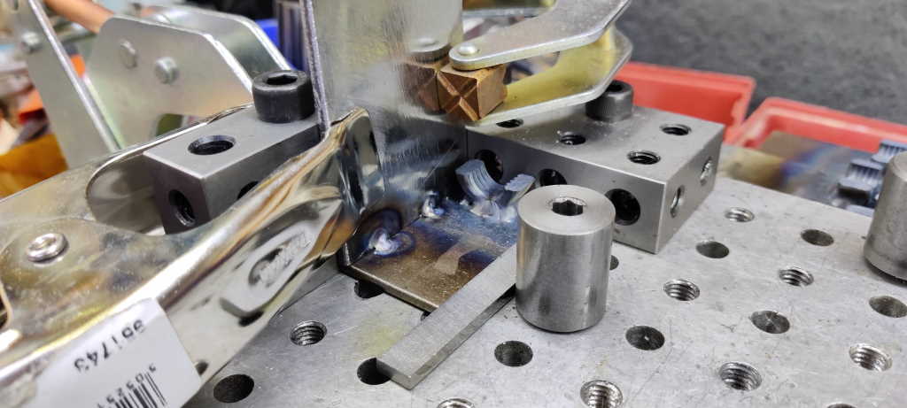
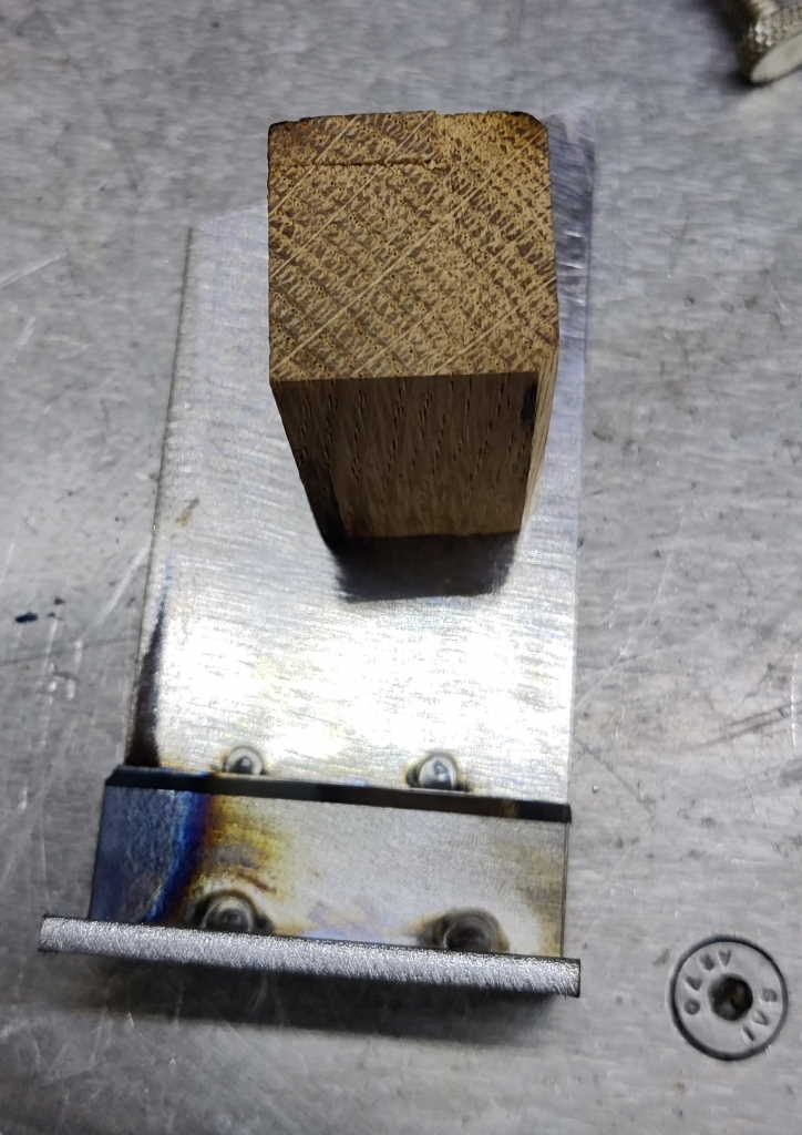
For the screw jaws, I used the same fixture, but put the small ledge pieces in at the same time. I had to use a different spacer between the base plate and the eccentric screw as the base plates are a bit narrower on the screw jaw. The plate is intended to be 3 mm × 31 mm × 50 mm, but I ran out of 50 mm wide plate so I made these out of 30 mm plate - hence they're 3 mm × 30 mm × 50 mm. The difference shouldn't matter as it just means there's a gap on the outer edge on one side: that gap can be filled up with a weld bead. The bottom two tacks in the second photo were done with filler rod to make a decent joint; the top two were done without filler to minimise the size of the weld: ideally I want these welds to sit within the radius of the box section that will slide along here.
After tacking the pieces together, I took the spring clamp off and welded the spacers together and to the frame on one end. I did this without filler, just because it was quick and easy to do so. Amazingly I didn't melt my 20-40-80 block when welding any of the frames!
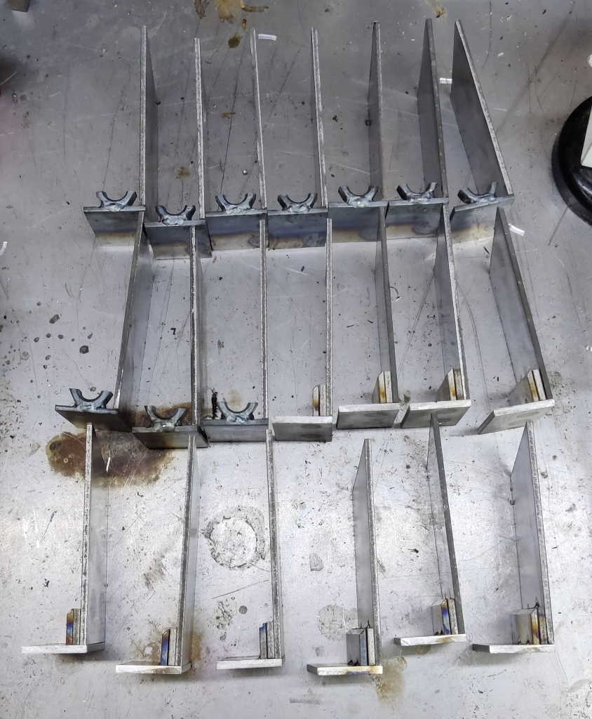 |
This photo shows what it all looked like with one side of each frame tacked in place.
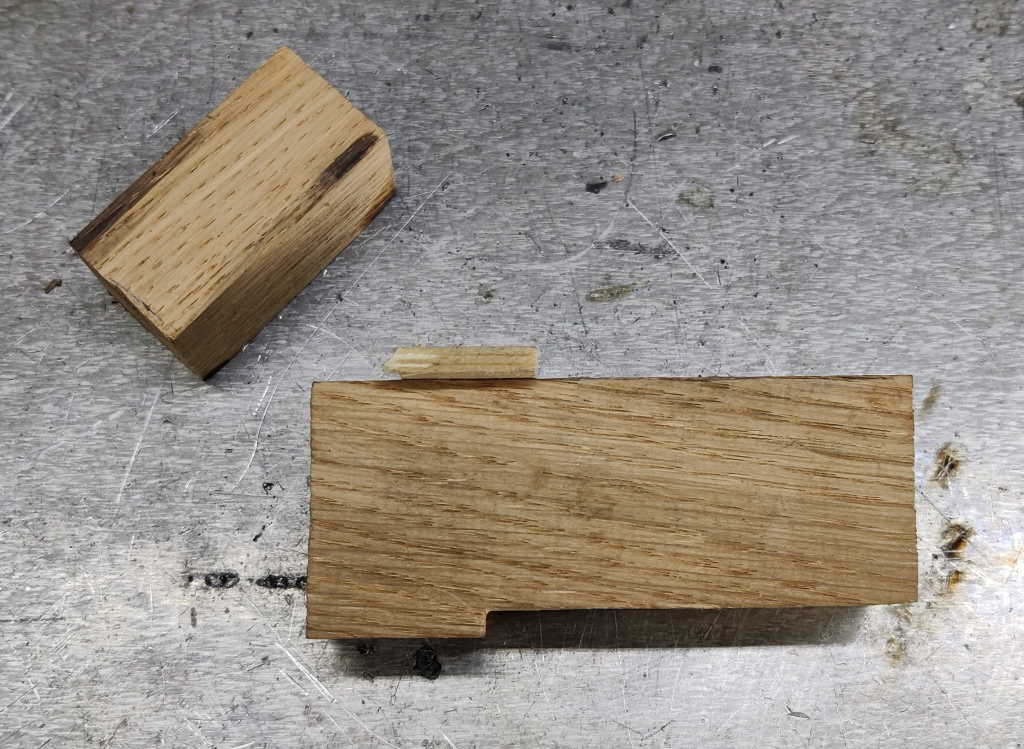 |
These two bits of wood were the "jigs" I used to complete the frames. They started out as one piece of oak that I hand-planed down to 25.5 mm thick. I then separated and shaped the two pieces. One is a 25.5 mm rectangular prism with one chamfered edge; the other has a ledge on one side and a scrap of pine nailed to the other side to help with assembly. When I made the prototype, I spent ages worrying about what angle to use for the sliding jaw assembly. In the end I realised it really doesn't matter that much - there's plenty of opportunity to tweak it after welding it together (filing the back to get it to sit horizontally and lowering the jaw piece to get the right drop height).
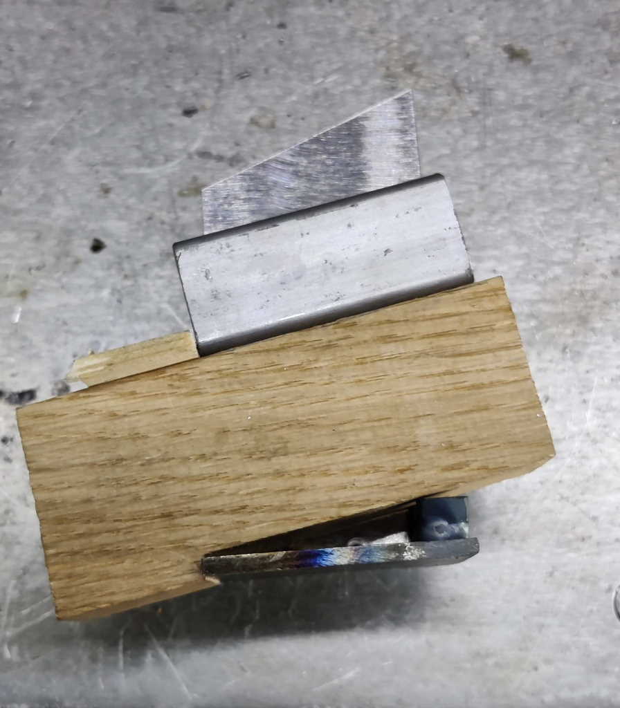 |
This photo shows how the jig helps with assembly. In practice, I don't fit the internal bit of box section until the frame sides are clamped together (it's thinner than the wood so can easily be slid into place), but I thought it helped for the photo. The box section will be ground down to match the width of the frame after everything is welded together.
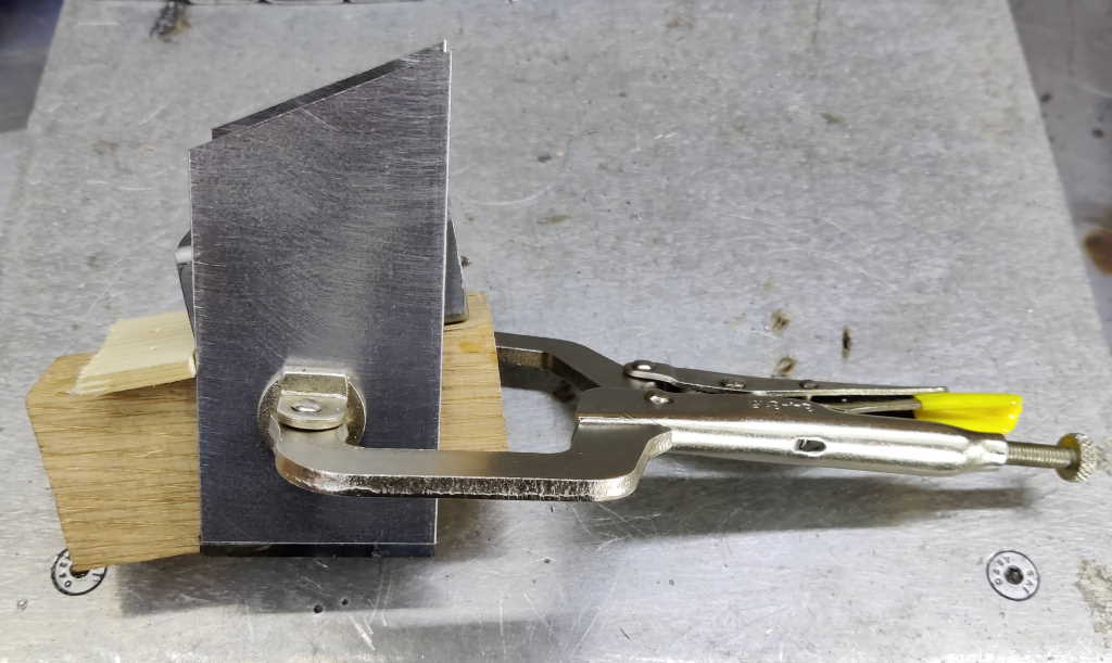 |
I used a C-clamp to hold the frame together to weld it. The box section is only held in by gravity here, but that's good enough to get some tack welds on the corners.
 |
This is what a sliding jaw looks like after tack-welding it together. At this point the C-clamp can be removed and the wood "persuaded" to come out by tapping it with a hammer. I'll come back to doing some proper welds later.
 |
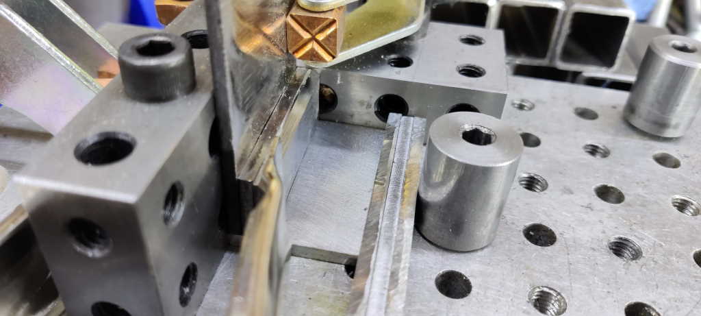
The screw jaw "jig" has a chamfer on one corner. That's there just to make sure it clears the tack welds on the frame and is about the same size as the radius on the corner of the box section it's emulating.
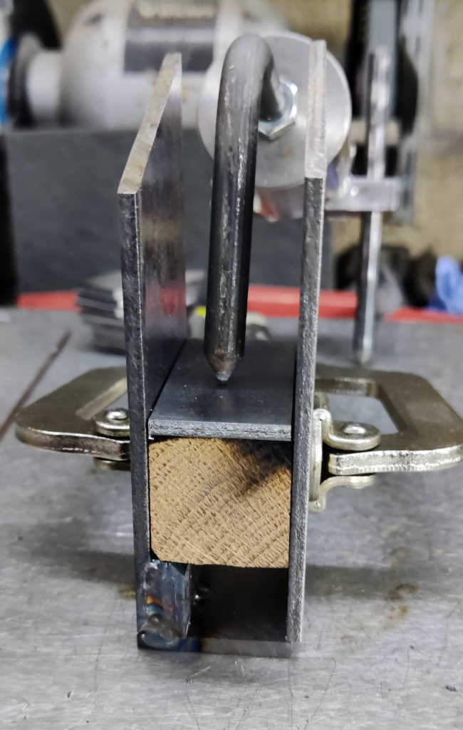 |
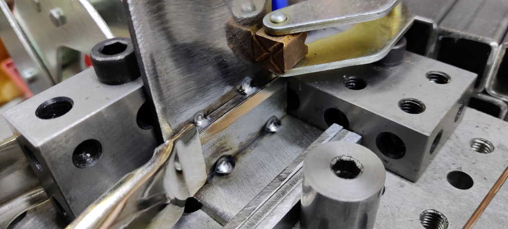
This shows the "jig" for the screw jaw frame being used. It's simply a spacer that ensures that the box section will slide easily through this bit of the screw jaw. The top plate is a lot lighter than the box section used for the sliding jaw, so I held it down with my welder's third hand.
This shows all the frames having been tack-welded together.
The last bit of preparation welding was to attach the other pair of ledge pieces to the screw jaws. Like the first ones, I did this without filler rod for speed and ease. They were held in place with spring clamps, so were quick to put together and doing all ten screw jaws took very little time.
This photo shows the jaw frames with the second set of spacers added.
That's it for today; I'll have to go back and finish welding all of the frames properly (rather than just having tack-welds everywhere), but I thought it was time to call it a day.
Page Navigation:
| First (#1) | Previous (#12) | Next (#14) | Last (#32) |
This website is free, but costs me money to run. If you'd like to support this site, please consider making a small donation or sending me a message to let me know what you liked or found useful.