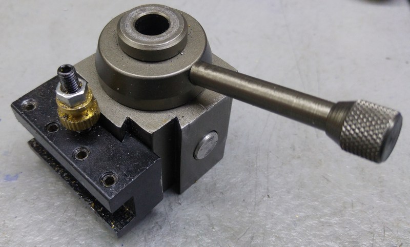
Quick Change Tool Post Mk 2
Background Information
My first Quick Change Tool Post has served me well for a few years and was a vast improvement over the four-way tool post that is supplied with the lathe. However, there are a few weaknesses in the design:
- It requires a hex key to fit the tool to the tool-post (this could be resolved with a custom locking screw, but one would be needed for each tool holder).
- The tool holders are not repeatable in location: when removing a tool holder and replacing it, the dial setting is lost. This rarely caused me a problem in practice as I don't often make duplicate parts, but once or twice it would have been nice to have repeatability.
- The tool holders are fairly time-consuming to make.
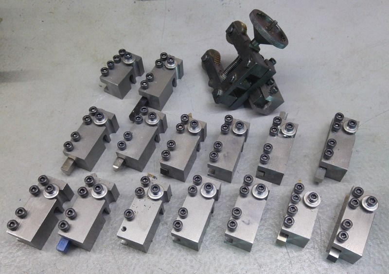
- The tool holders take a lot of space so are difficult to store in a way that is easy for quick access.
- The tangential tool holder does not retain its setting through tool sharpening as there is no reference surface for re-fitting the tool into the holder.
The big advantage of the design was that it could be made on a small, low-power lathe and a pillar drill. Now that I have a milling machine, though, I felt it was time to look at alternative options.
A Bad Idea
It took me a while to build up to the idea of replacing all of my tool holders and I saw a tool post designed for the mini-lathe in an auction on ebay. This type of tool holder is available from a number of sellers and is based on a piston-type tool post with a dovetail. The tool holders and the tool post are made of aluminium. What I discovered was that buying this tool holder was a waste of money: the tolerances to which the post and holders are made are very wide and the piston type of tool post is not very tolerant to inaccuracies. Every time the tool holder is fitted to the tool post it will sit in a different location, in terms of tool height as well as XY position. I managed to make it a bit better by glueing a copper shim to the tool post dovetail, but it was still a bit poor quality and frustrating to use and I quickly went back to my simple pillar tool post.
A Good Idea
Eventually, I decided it was time to look at making my own tool post and had settled on the idea of making a dovetail tool post that pulls the tool holder back into the tool post (rather than pushing it away). Then I discovered a tool post listed on Harold Hall's website that used a different approach - a cylindrical reference on the tool post which mates with a reamed slot in the tool holder. This looked like an interesting idea and I thought it was worth a try!
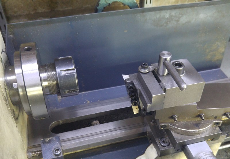
This is my version of Harold's tool post mounted to my lathe with my new tangential tool holder fitted. I'm not going to give all the details of the design of this tool post and the tool holders as they are described in excellent detail on Harold's site, but I will note a few modifications I made to the design and manufacturing methodology as I was making the parts.
Repeatability
One of the issues I listed with my previous tool post was the lack of repeatability of the tool holders. Since this design was supposed to offer better repeatability, I thought it would be a good idea to measure it.
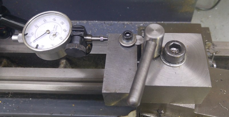 | 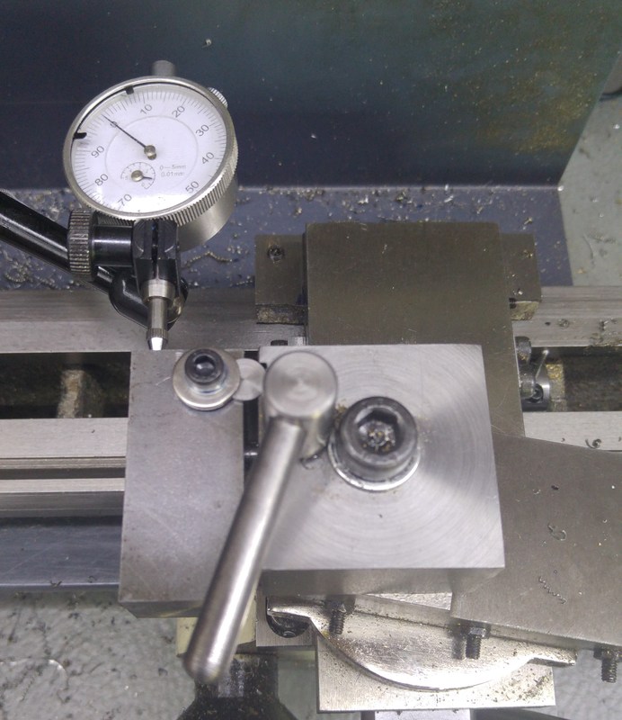 | 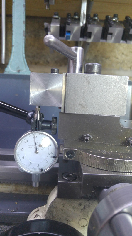 |
My method for measuring repeatability was fairly simple. Lock the carriage and all the slides, then use a dial gauge to measure the position in each axis through a few attempts at inserting and removing a plain tool holder. My results were as follows:
| Axis | Maximum deviation |
|---|---|
| X | ±0.005 mm |
| Y | ±0.005 mm |
| Z | ±0.01 mm |
It was obvious that the X and Y measurements were subject to how consistently I could apply torque to the tommy bar, but getting consistent results was not difficult at all. I suspect the increase in deviation for the lathe tool height (Z axis) could be improved by holding the tool holder firmly down while tightening the tommy bar, but I was happy enough with the results as they are not to worry unduly.
Modification - More Clearance
One modification to the design I didn't do when I made the first batch of tool holders but corrected when I came back to make a couple more is to reduce the length of the tool holders to 55 mm instead of 60 mm. I've retained the overhang of the tool holder at the rear of the tool post (as it is useful for getting a grip on the tool holder when removing it), but removed the overhang at the front of the tool post as it reduces the maximum turning diameter on my little mini-lathe.
Modifications - Simplifying Manufacture
Drilling and Reaming the Tool Holders
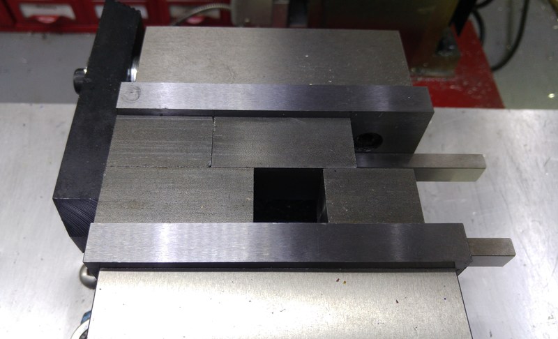 |  |
There are a couple of relative tedious operations and a lot of complex set-ups that are suggested by Harold. My milling machine now has a digital read-out so I decided to take advantage of this by making a lot of the holes in a single set up for each pair of tool holders. Using the same EN1A bar as used for the tool holders, I made a simple block that was reasonably accurately 25 mm × 25 mm × 34 mm (and a new one that was 39 mm long for the 55 mm tool holders). This was used to space the two tool holders from one another so that the bottom of both could be accessed at the same time and holes E, B, D and the reamed reference surface could all be machined in one set-up (see the tool holder drawing on Harold's site). The photos above show a before and after view of the main drilling and reaming set-up. The block in the bottom right is a 25 mm × 25 mm spacer used to improve the clamping of the upper-right tool holder.
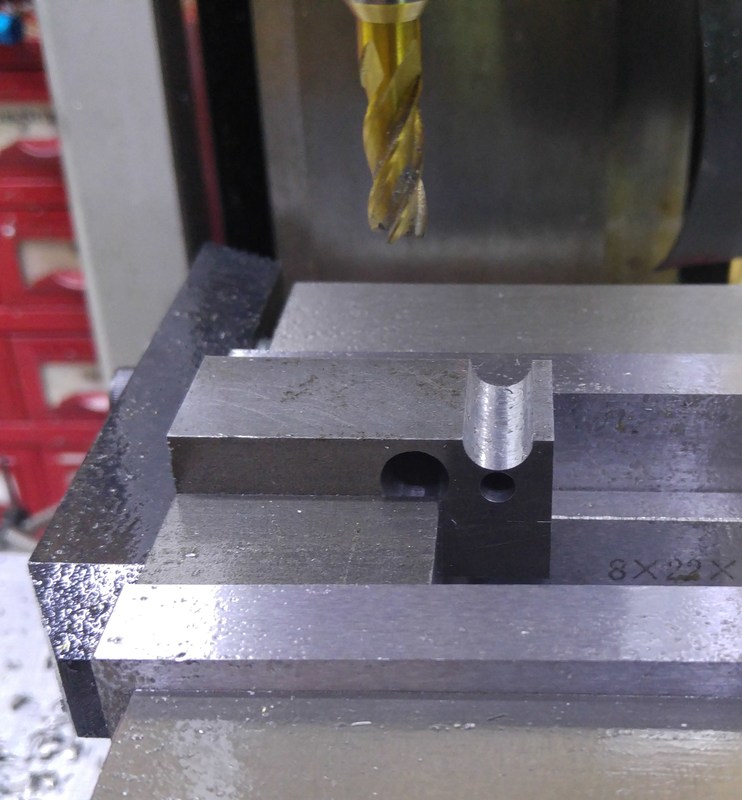 | 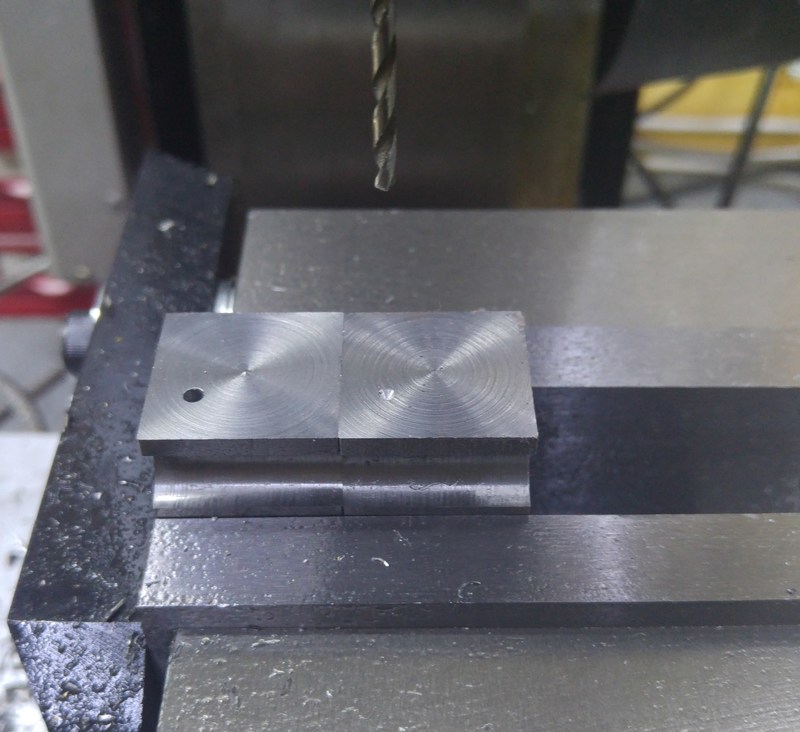 |
The same vice end-stop is then used for milling the slots and also drilling the grub-screw holes. In the left-hand photo note the use of two different size parallels (12 mm and 22 mm - only the 22 mm one is visible in the photo) to give access to the hole. I could have done this by closing the vice further and just using the higher parallel, but this was more convenient when making multiple tool holders. In the right-hand photo, the set-up is used to give a simple zero reference for the side nearest the camera enabling the hole to be accurately located in the Y-axis. The X-axis position is less critical so is aligned by eye.
Locating Key
The locating key is specified as being turned from 12 mm bar, reduced on the lathe to 9.995 mm and as close as possible to parallel. I had some stock of 10 mm silver steel and measured its diameter with a micrometer. It was 9.996 mm, which was good enough for me so I used this as the base material, which made the manufacturing process very straightforward.
Spacer
I made the spacer 10 mm × 3 mm × 32 mm instead of 8 mm × 3 mm × 32 mm, but only because I had some 10 mm × 3 mm material lying around - I don't think the width is especially critical.
Height Adjustment
As I was making a lot of tool holders, there were a couple of parts I really wasn't looking forward to making lots of: the height adjuster washer and the small piece of copper placed under the grub screw (see the description on the last page of Harold's description).
For the height adjuster washer, my first thought was just to use a flanged button head M5 screw (which have a maximum diameter of 11.8 mm according to ISO 7380 F). However, the ones I ordered were closer to the minimum diameter of 11.1 mm and this isn't really suitable. As an alternative, I found a supplier on ebay of 4.3 mm × 15 mm × 1.5 mm washers (note many suppliers offer these washers with a thickness of only 1.2 mm). The inner diameter is fairly close to the tapping diameter for M5 and the thickness is sufficient for a couple of turns of thread, so I decided to try these and hand-tap them to M5. To account for the small section of unthreaded shaft near the head of M5 screw (the reason for the small counterbore in Harold's drawing), I simply added a normal 1.2 mm thick M5 washer. They work brilliantly and are much quicker to make than the thick 12 mm turned washers. An even quicker option might have been to buy some 5 mm × 15 mm × 1.5 mm washers and use some Loctite 603 to attach them to the screw head, but I'm quite happy with the threaded washers.
The grub screw is used to fix the height of the height adjusting screw and hence it doesn't experience much load (unless you put a hex key on the adjusting screw and try hard to turn it). The piece of copper is used to protect the thread on the height adjusting screw when the grub screw is tightened. As an alternative to this approach, I bought a large bag of 12 mm long M3 nylon grub screws. These can be screwed fairly tightly against the height adjusting screw without damaging its thread and they work well at preventing unwanted rotation. They can also be easily adjusted in length with a pair of side cutters.
Modification - Increasing Strength
One concern I had with the design was the lack of material around the cam in the so-called operating piece. This is a 10 mm shaft with an 8 mm hole drilled or reamed in it. This leaves a 1 mm sliver of steel either side of the hole (assuming you drill the hole perfectly centrally) to ensure the tool holder doesn't move. I was concerned that if I did something silly like try to cut too deeply, this would be the point that would break (I've made the mistake of under-sizing shafts in a similar situation before). There's loads of material around this hole in the body, so I could see no good reason not to increase the diameter of the operating piece to 12 mm. It has worked very well and I can't see any disadvantages to this.
Modification - Simplifying Use
In Harold's design, the locking spindle is operated by a tommy bar which is mounted in the back of the tool post body and fitted as required. I decided to increase the diameter of the top part of the locking spindle (in two stages to give space for the mounting washer) and permanently attach an 8 mm bar so it is always available.
Modification - Different Tool Holders
Square Shank Tool Holders
In Harold's design, all the tool holders have a 14 mm × 10 mm slot milled 5 mm from the base for a tool. The vast majority of the tools I use on the mini-lathe are either 8 mm or 5/16" (7.938 mm) square. The size of the mini-lathe is such that you can just fit a 10 mm tool holder if the slot starts at 4.5 mm from the base. Therefore, I used this as the base dimension and made a few tool holders with a 12 mm × 10 mm slot and a lot of tool holders with a 10 mm × 8 mm slot for my 8 mm tools. I made one tool holder with a 14 mm × 12.7 mm slot to hold my knurling tool (which has a 1/2" square shank). In general, the narrower slots have the advantage of an increased thread length in which the M5 tool holding screws are fitted.
Slotless Tool Holders
I also made 8 tool holders with no slot at all for later customisation. These were for holding tools with something other than the normal square shank.
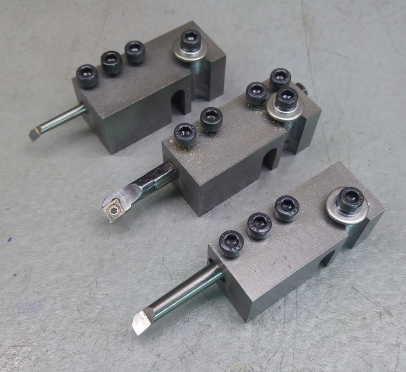
Three of these slotless tool holders were used for boring tools - a hole was drilled in the end and then screw holes were tapped in much the same way as those that hold the normal tools in place.
One of the plain tool holders was fitted with two bearings for nudging the work piece into line. This is based on a concept described well by Chris from clickspringprojects.com.
One of the plain tool holders was fitted with a 1/2" × 1/16" parting blade.
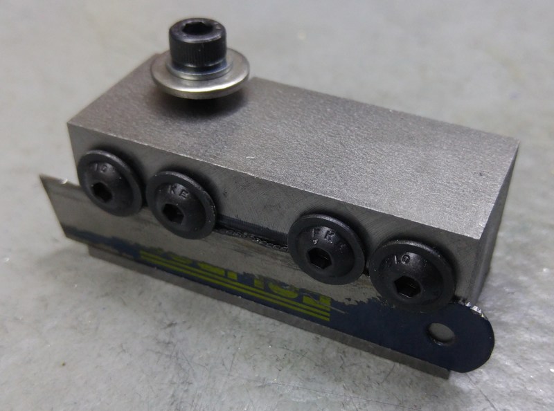
One tool holder was made into a hacksaw blade holder based loosely on the design by Mike Cox. At the bottom of the blade, an undercut has been made with a 60° dovetail cutter. The hacksaw blade is held at the bottom by this undercut and retained by four ISO 7380 F flanged button head M5 screws at the top. These were positioned by eye after holding the blade in the undercut.
The rest of the slotless tool holders are spares for applications that will no doubt present themselves in due course...
Tangential Tool Holders
Finally, I made two new tangential tool holders. These are described on a separate page.
Tool Holder Storage
As I mentioned at the top, one of the disadvantages of my previous tool post was the space occupied by all the tool holders. Having completed the tool holders, I made a convenient storage shelf for the new tool holders - see this page for more information.
Drawings etc
I have made 3D models and dimensioned drawings for all of the parts I've designed (e.g. the tangential tool holders and the tool holder storage frame) or modified from Harold's designs (e.g. the increased diameter operating piece and the new locking spindle). Please use the contact form to get in touch if you're interested in any of these drawings (but please be sure to let me know which ones you want).
This website is free, but costs me money to run. If you'd like to support this site, please consider making a small donation or sending me a message to let me know what you liked or found useful.
