QCTP Tool Holders
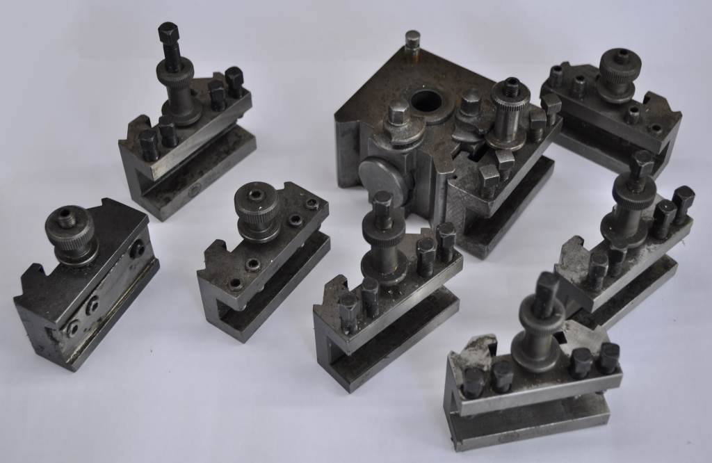 |  |
My Harrison M250 came with a Dickson tool post and six tool holders. These tool holders are well made and robust, but have a very limited adjustment range. Fitting a 12 mm HSS tool requires a 4 mm shim underneath the tool to bring it up to centre height. The geometry of the tool holders also suggests some fairly critical dimensions and a very complicated manufacturing process given the tools I have available. From a usability point-of-view, I preferred my home-made mini-lathe tool post.
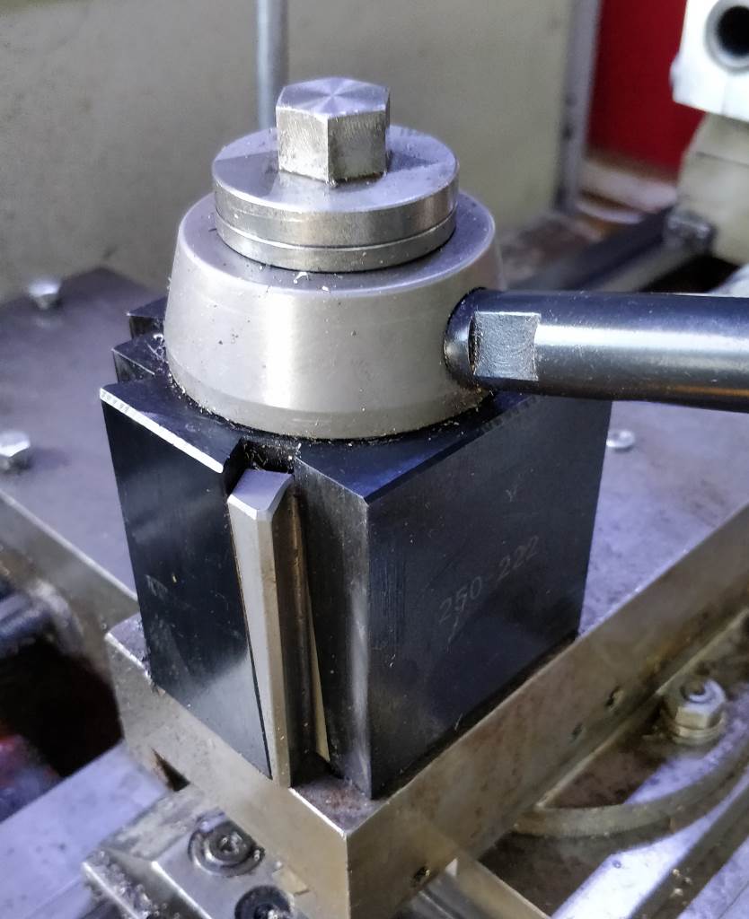 |  |
I therefore decided to replace the tool post with a (Chinese manufactured) copy of an Aloris BXA "wedge-type" tool post. This uses a simple dovetail to align the tool holder and the tool post. The wedge-type (which is superior, in my opinion, to the piston-type) tool holder has a sliding wedge on one side of the dovetail to pull the tool holder against the outer faces of the tool post. You can see the movement of the wedge by comparing the left-hand photo above and the one at the top-right of the page. This design allows for a small amount of variation in the size of the tool holders's dovetail while ensuring that it is always held in a consistent location and alignment. This has allowed me to make a lot of my own tool holders (you can never have too many in my opinion). The ones shown in the right-hand photo above are all of the ones I've bought (rather than made) for the tool post.
 | 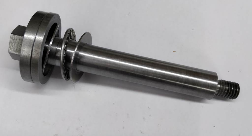 |
These photos show the screw I made to fix the tool post to the M250. I have to admit that this is a slightly ridiculous design. I didn't have any bar stock anywhere near 16 mm diameter at the time that I was making it, so, rather than having a sensible diameter with a big washer at the top, it has been turned from a piece of 40 mm bar. The end that fits into the lathe is threaded M10; the top end was milled to form a 17 mm across-flats hexagon. Most of the shaft length is 16 mm diameter; there is a short section near the "washer" that is 17 mm diameter. A thrust bearing (consisting of the two thin washers and bearing itself) sits on the 17 mm section (which is shorter than the length of the assembled thrust washer). The other component shown rightmost in the left-hand picture protects the thrust washer from swarf. The right-hand picture shows the parts put together ready for use (as with all photos on this site, click on the photo for a bigger view).
 | 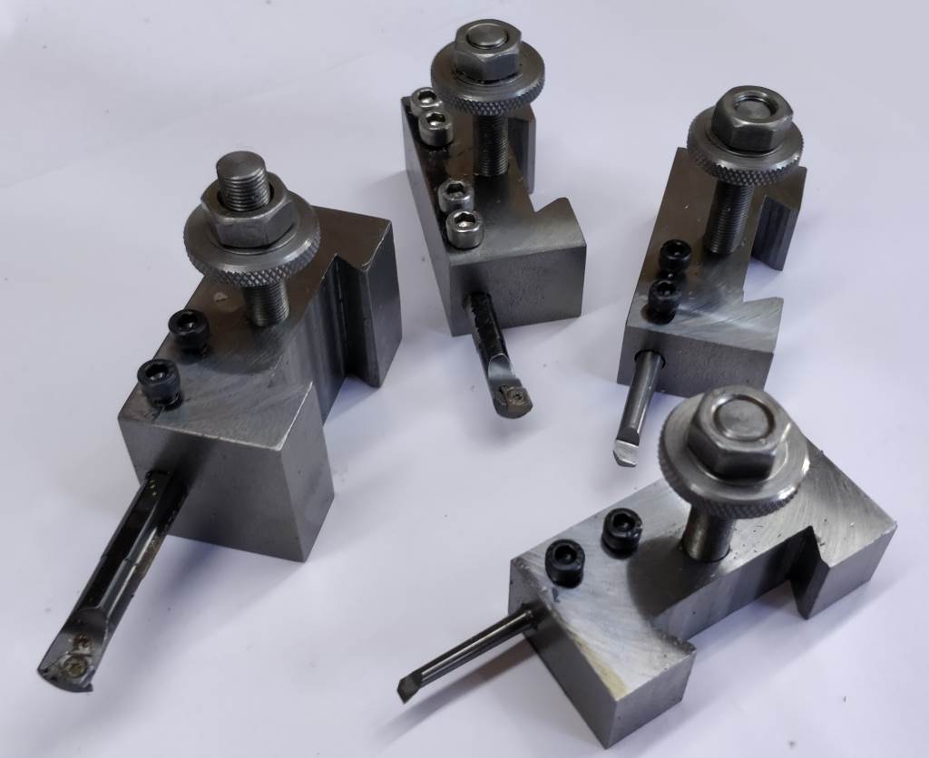 | 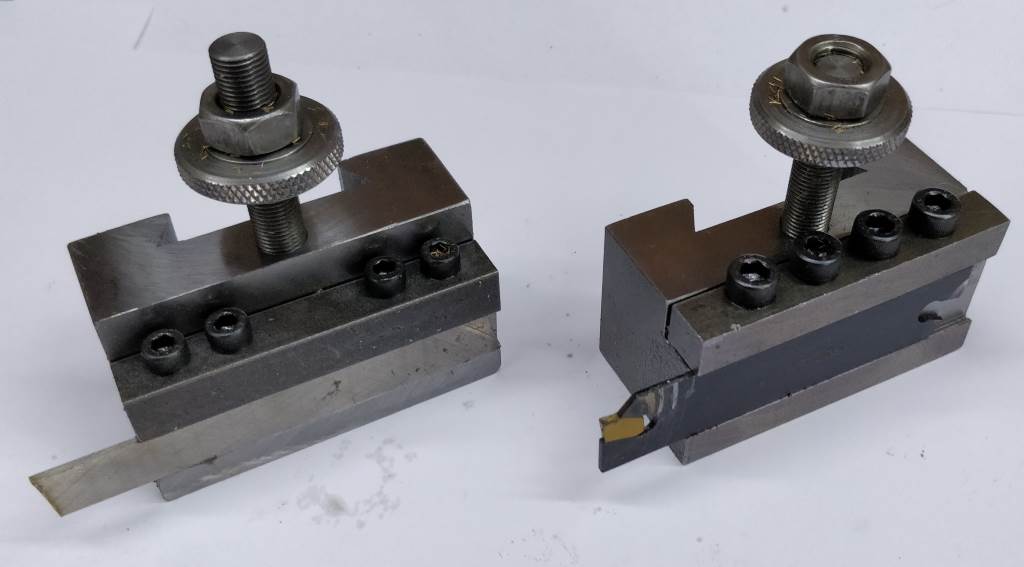 |
The pictures above shows a selection of the tool holders I've made to date. At present, I have a total of 34 holders:
- Six commercial (bought rather than made) tool holders with a 16 mm high, 12 mm deep slot and a V-groove cut in them to hold round tooling.
- Thirteen home made tools with a 16 mm × 16 mm slot.
- Four home-made with a 16 mm × 12 mm slot.
- One with a 10 mm × 8 mm slot for holding 8 mm (or 5/16") tools. At some point I might increase the size of the slot in this tool holder for larger tools as I have since made a set of small tool holders for holding 8 mm tools in a 16 mm slot - these allow the tool to stick further out from the toolpost without being as flexible as a 8 mm tool held directly in a tool holder.
- One bearing block - see notes below.
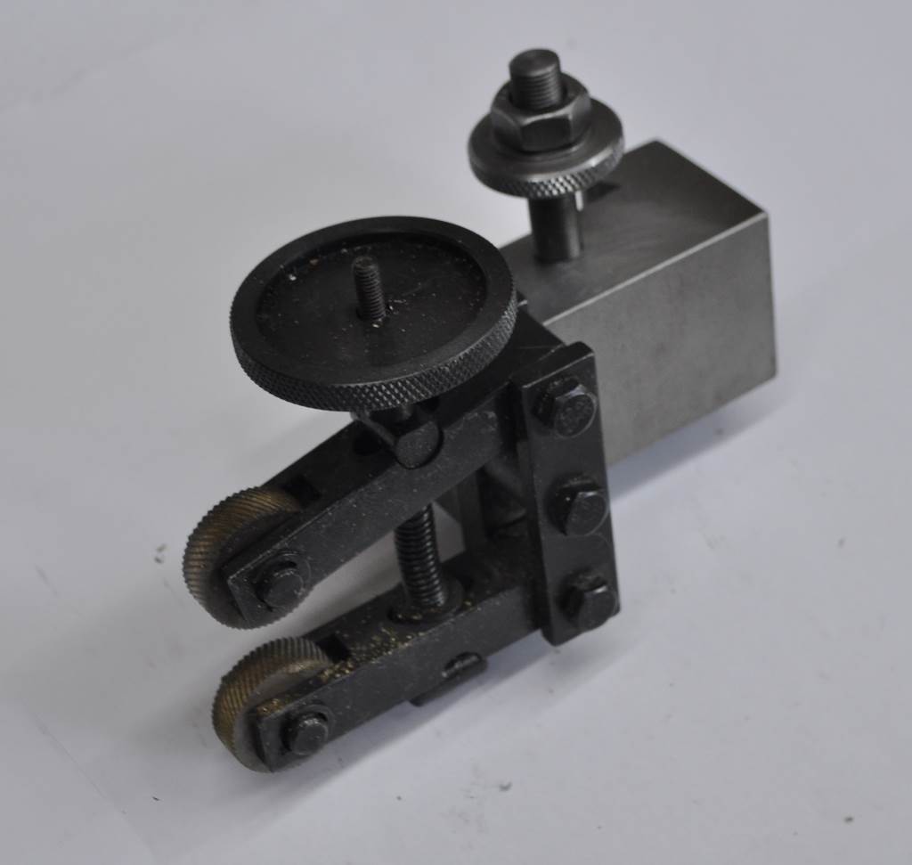
- One knurling tool - shown below.
- One tangential tool holder - shown below.
- One dial indicator holder - shown below.
- Two parting tool holders: one with an HSS parting blade and one with a carbide insert parting blade.
- Four boring bar blocks of various bore sizes.
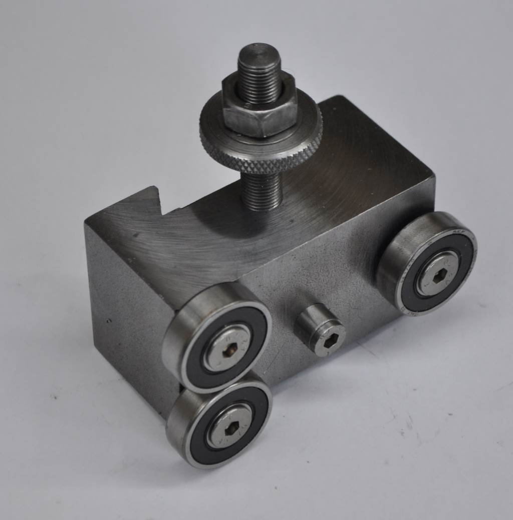 |  |
The photograph on the left shows the bearing block for pushing work to run true. This is a slightly unusual design in that it's intended to be usable both for pushing work to run true and also to straighten slightly bent bar stock. Mounted in an orientation such that the single bearing is in line with the ways, it can be used in the conventional manner to push against the face of a work piece. In the other orientation, two bearings press against the part. This makes the manufacture slightly more complicated as it is essential that the two bearings both reach the work at the same time and that the mid-point of the bearings is exactly on centre height. The small cylindrical component in the middle of the tool is positioned such that the top of the cylindrical component is exactly on the centreline of the two bearings. My tool height gauge can then be used when setting up the tool holder to ensure that it sits exactly on centre. The centres of the three bearings and the cylindrical height setting piece were located (and drilled) using the DRO on the milling machine.
The photograph on the right shows a knurling tool. This is a commercial knurling tool that was dismantled to remove the bar that would normally be held in a tool holder. The upright piece was then bolted directly to a home-made tool holder.
 | 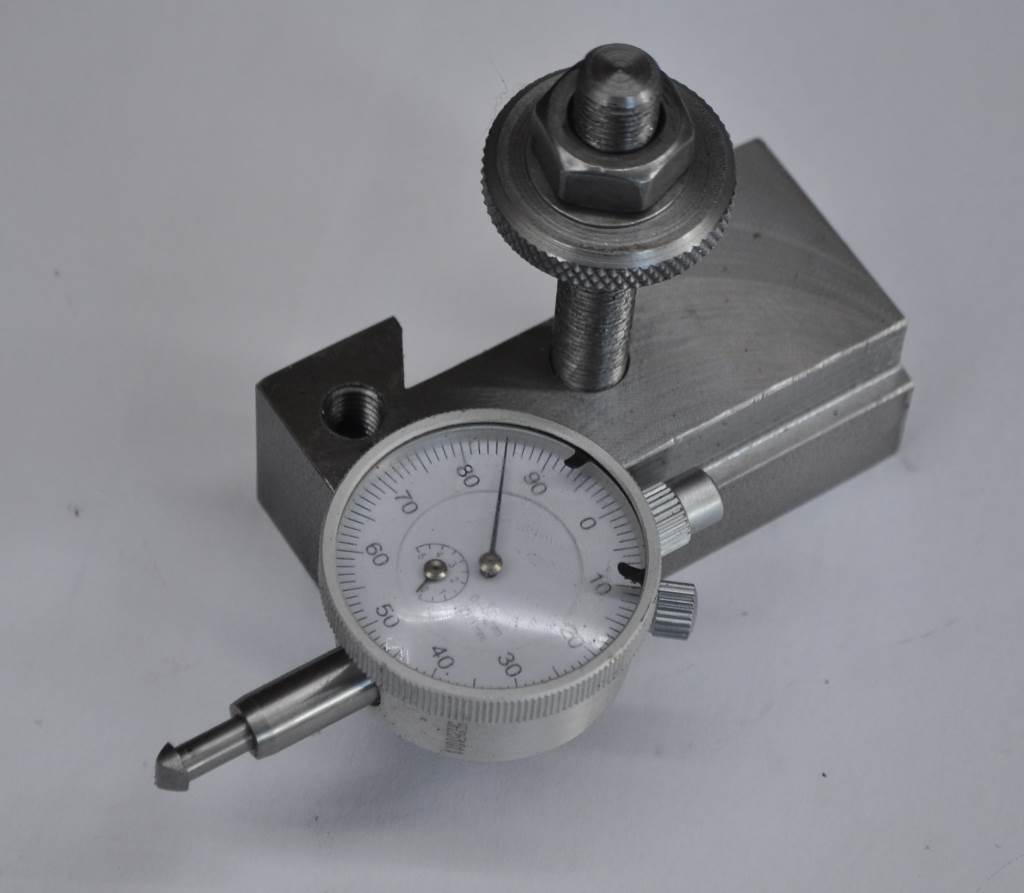 |
The photograph on the left shows a tangential tool holder for the M250. This was made by dismantling the first tangential tool holder that I made and fixing the tangential holder to a blank BXA holder. The right hand photograph shows a dedicated tool holder for a dial indicator. This holds the dial indicator on centre height and is used for setting tapers accurately. A custom tip for the dial indicator has been added. This was made by turning a plain cylinder with a short M2.5 threaded portion. It was fitted tightly to the dial indicator and the orientation noted. It was then shaped into a wedge with a hand file.
Storage
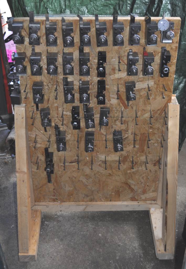 | 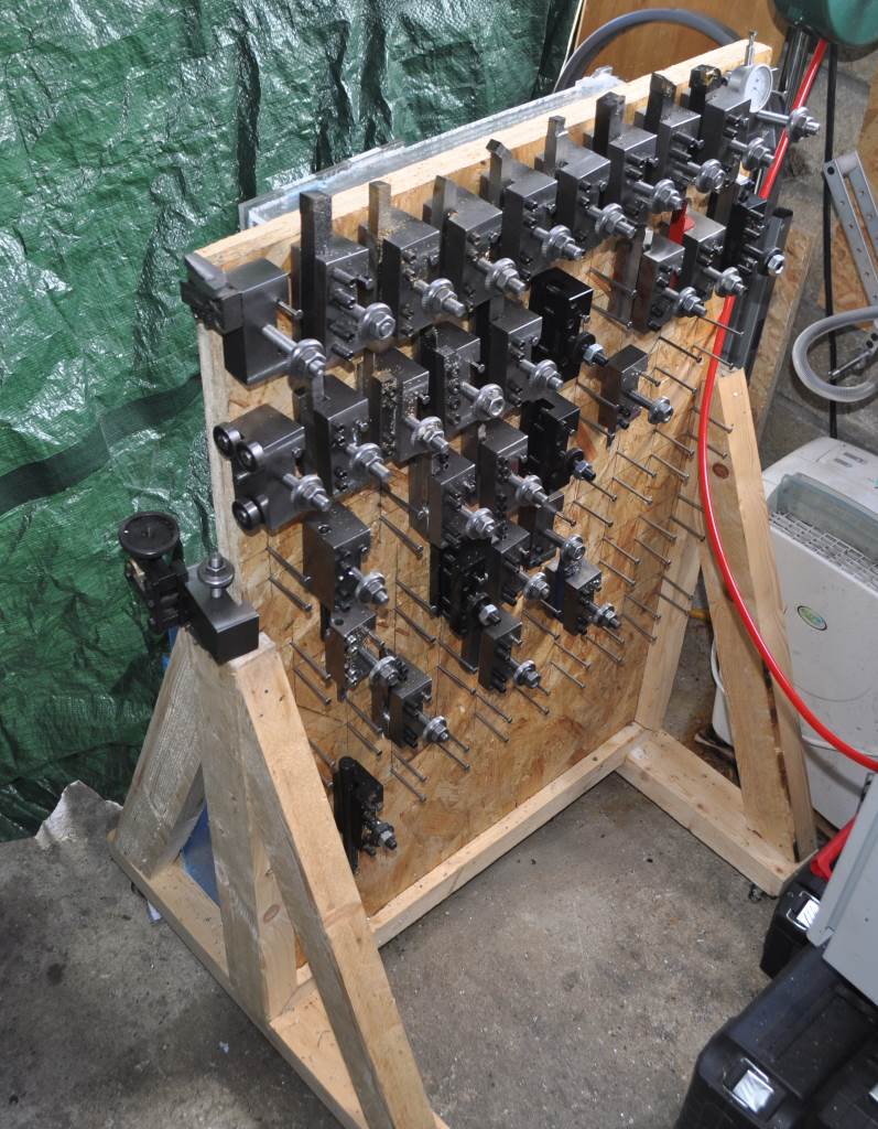 |
The BXA tool holders for the Harrison M250 are a lot bigger than those for my mini-lathe. With 34 tool holders, the space requirement is fairly high and I didn't want to use up a lot of bench space or even wall space. Therefore, I decided to make a movable rack for storing the tool holders. Construction is relatively simple. The panel is made from a sheet of 2440 mm × 1220 mm × 18 mm OSB (from B&Q), cut up and with two pieces tacked together with panel pins (most of the rest of this sheet was used for my bar storage unit. The sheet size after cutting was 3' × 2' (914 mm × 610 mm). A grid was drawn on the panel with a pencil and a 1 m aluminium ruler and 65 mm nails were added to support the tool holders. The rest of the structure was cut (with a hand-saw) from a single length of 3" × 2" (75 mm × 50 mm) pine. Slots for the upright panel were cut with a circular saw and then everything was glued together. Castors were added on the four corners so that the holder rack can be wheeled out of the way when not in use. The green tarpaulin that you can see hanging down behind the rack is there to protect my motorbikes (which take up the half of the garage that isn't workshop) from flying swarf.
Storage Update
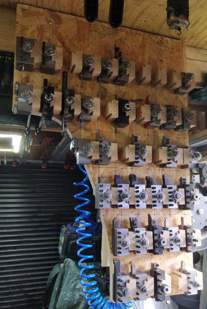 |
I have since modified the tool holder storage such that it is attached to the ceiling rather than running on castors. You can see the modified version in the photo above. The cut-out in the bottom-left gives me room to walk past it!
 |
The toolholders now sit on these mount blocks rather than nails. The mount blocks are made out of Cedar of Lebanon and were made using my table saw.
Manufacturing Process
The tool holders were machined from 3" × 1.5" (approximately 75 mm × 38 mm) EN1A mild steel flat bar (I couldn't find a local supplier of EN1A flat bar in metric sizes). The process I used to make the tool holders was as follows:
- Mount 200 mm (ish) long length of bar stock in vice on 12 mm high parallels with about 30 mm protruding from the left-hand side (assuming the vice is where I normally leave it).
- Set DRO 0 to Y-axis centre.
- With 16 mm diameter insert carbide tool in collet chuck or R8 cutter holder, cut a centred 36 mm wide slot 11 mm deep. Cut in 1 mm Z steps; cut two slots (bidirectional milling) at ±10 mm, then remove the middle 4 mm section in 2 mm Z steps. Cut at top mill speed and slow power feed speed.
- With 25 mm OD dovetail cutter in collet chuck or R8 cutter holder, set height to 10.5 mm below top surface. Cut at ±6 mm, then in 0.5 mm steps with the cutter running clockwise around the slot. When 9 mm is reached (and possibly before), cut with the Y travel locked. Cut to ±9.35 mm with the last pass in the opposite direction (cutter running anticlockwise around the slot), then increase on one side until 28.4 mm is measured between 6 mm dowel pins.
- With a fly cutter, skim the top (taking 0.25 mm per pass maximum and 0.1 mm when getting close) until the tool post slides relatively easily.
- Remove from mill and slice up.
- Mount three-at-a-time in the vice for facing to length.
- Measure each block (and keep together the blocks that were faced together).
- Mount three-at-a-time with an end-stop in place. Do this with the same sets as faced in the earlier step. Orientation should be such that the Y-axis zero remains correct.
- Find the edge that the mill-stop is touching and zero in X.
- Using the block length measurements of the block sizes, drill 9 mm to no more than 10 mm depth at 0.5×length, 1.5×length and 2.5×length.
- Carefully power tap M10×1 with spiral flute tap.
- Cut slots and M8 threaded holes for clamping screws as required for the intended use of the tool holder.
Any left-over lengths of the dovetailed stock (after cutting out pieces of typical tool holder size) were kept and used for "special" tool holders like boring bars and the dial indicator holder.
This website is free, but costs me money to run. If you'd like to support this site, please consider making a small donation or sending me a message to let me know what you liked or found useful.