Bar Clamps Build Process
14/5/2021
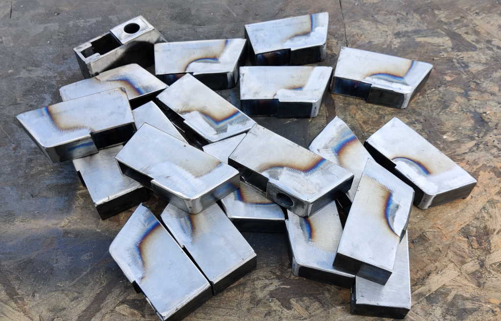 |
I'd debated whether to leave the welded outer corners with the weld beads visible or round off the corners, but in the end I decided to give them all a quick go with an 80 grit flap disc in the angle grinder to round everything off nicely.
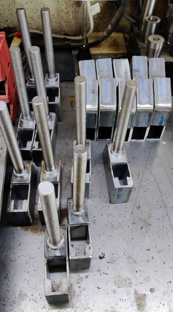 |
The jaw pieces could then be fitted to the frames. In the case of the screw jaw frame, the threaded rod has to be inserted before attaching the jaws, but it doesn't need to be welded in place, so for now I've just hand-tightened the other split nut onto the threaded rod to hold it in the hole.
To choose a place for the jaws, there are a few options:
- Line up the bottom of the jaw piece with the bottom of the cross-piece (in the case of the screw jaw, this is the 3 mm × 25 mm × 50 mm plate and in the case of the sliding jaw this is the bottom edge of the internal box section). This has the disadvantage that the two jaws won't line up with one another, so it's probably best to trim one of the jaws down to match the top of the other. This was my approach for the prototype.
- Line up the bottom of the jaw piece of the sliding jaw with the bottom of the box section and then line up the bottom of the jaw piece on the screw jaw with the jaw piece of the sliding jaw.
- As per the previous option, but lower the jaw piece of the sliding jaw until it is at the lowest height that still allows the half-nut to disengage from the threaded rod.
The advantage of the last one is that the bottom of the jaw will be as close as possible to the box section (and parts are likely to be resting on the box section for clamping); the disadvantage is that when sliding it, there won't be two flat surfaces sliding together: it'll be two edges sliding on a flat surface. I don't think that's an issue, so I went with the last option. I did, however, lightly chamfer (with a flap disc in an angle grinder) the rear edges of the jaws to give a slightly smoother running surface.
To work out the position of the jaw pieces, I fitted a jaw piece to a sliding jaw and held it in place with a clamp. I checked whether the jaw could disengage and kept lowering the jaw until it couldn't any more. I then moved it back up until it could just disengage and measured the distance from the bottom of the frame to the bottom of the jaw piece. This worked out as 46 mm. I added a little bit for a safety margin and then cut a spacer to the resulting size: 48 mm. This could then be used as a reference when tacking the jaw pieces in place.
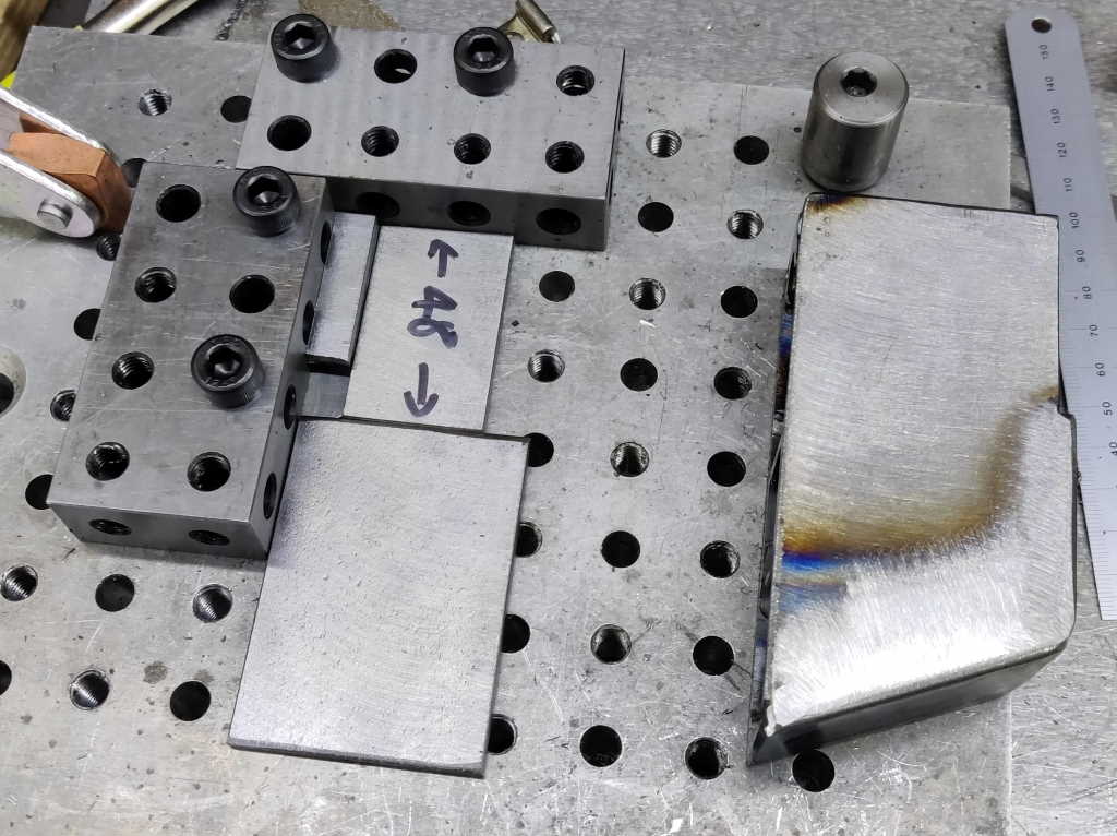 |
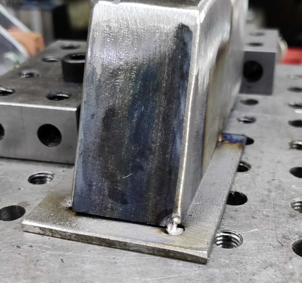
This photo shows the jig I used to tack the jaws in place. It's based on the same fixture plate I used earlier in the project. The two 20–40–80 blocks give a right-angle reference. The two small blocks (one on top of another) are offcuts that happened to be about the right size to offset the body and get the jaw centred. They're held in place with double-sided tape and there needed to be two (actually one cut in half) due to the fact that the body is raised up by the thickness of the jaw. The spacer (marked with its size) sets the offset for the jaw relative to the base of the jaw frame.
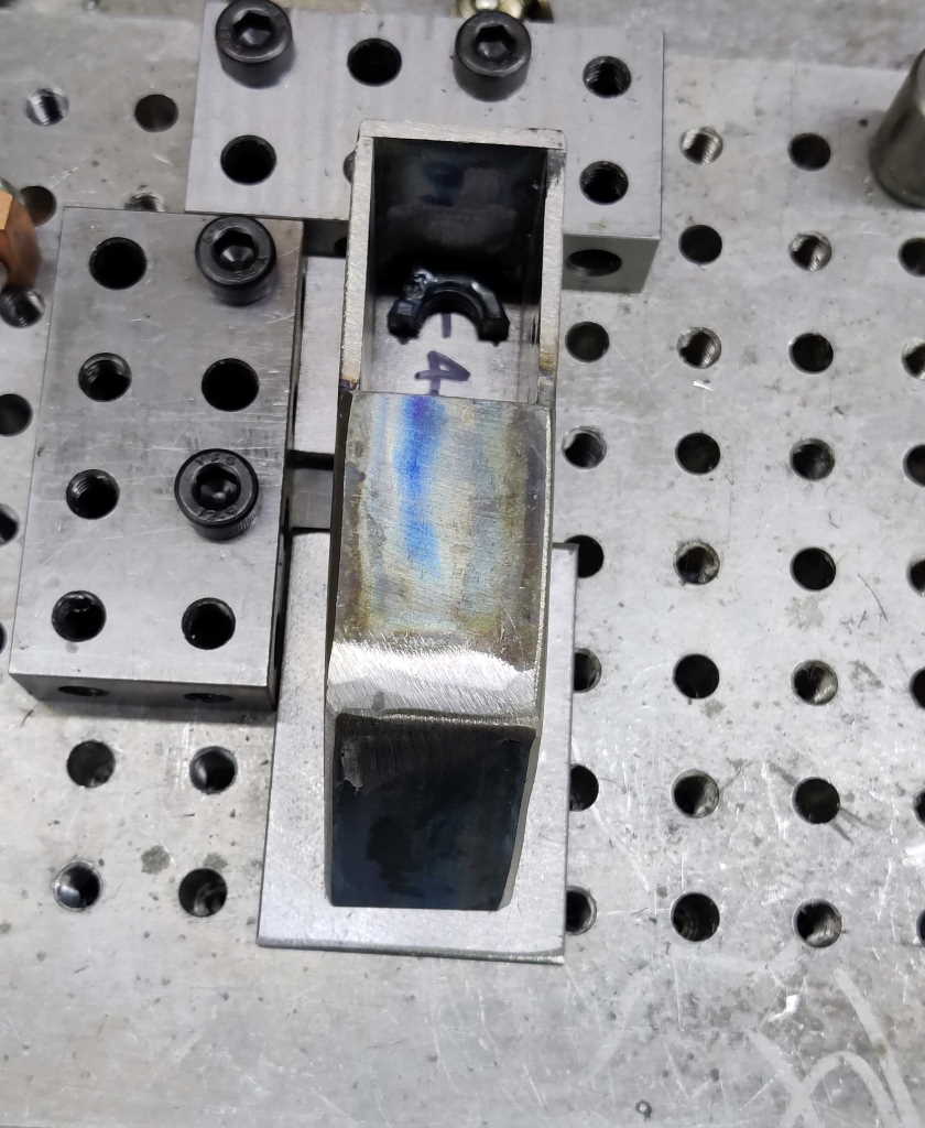 |
This shows one of the jaws sitting on the jig ready to be tacked in place. Hopefully this shows what all the bits are doing. With the body held down onto the jaw with my left hand, I placed a tack in one corner and then placed further tacks in the other three corners (it doesn't need to stay held in the jig for the other three tacks).
 |
This shows what the jaw looks like with the tacks done.
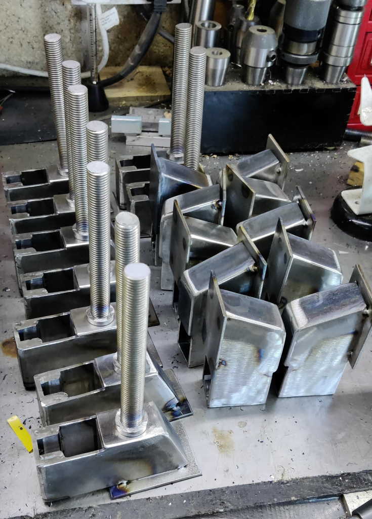 |
So far, I've tacked all the jaws in place; tomorrow I'll weld round the three sides of the join to complete the frames.
Page Navigation:
| First (#1) | Previous (#17) | Next (#19) | Last (#32) |
This website is free, but costs me money to run. If you'd like to support this site, please consider making a small donation or sending me a message to let me know what you liked or found useful.