Bar Clamps Build Process
12/5/2021
With all the jaw frames sorted, I could get on with welding. I started by fitting all the back plates. Note that, in the case of the screw jaw, this is a different sequence to the one used by Neil Paskin - he attached the M16 threaded rod to the plate before welding it into the screw jaw. I decided that switching the order around would make it easier as the plate doesn't have a bit of rod flapping around making it awkward to weld.
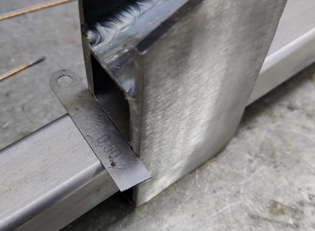 |
I started with the sliding jaws. For all but one of these, I placed them on the prototype bar (with the half-nut engaged and the jaw frame sitting parallel with the bar) and used a small piece of feeler gauge as a spacer. I've got loads of these little pieces as I bought three super-cheap feeler gauges about 10 years ago and cut them up for use as shim stock when using the four-way tool post that came with my mini-lathe. Now I just use them for odd jobs like this.
 |
The back piece could then be placed on top of the feeler gauge stock, clamped in place and then tack welded. After the first few, I switched from using the cantilever clamp shown in this photo to using a C-clamp as the pliers-style action of the C-clamp is much quicker and easier one-handed.
 |
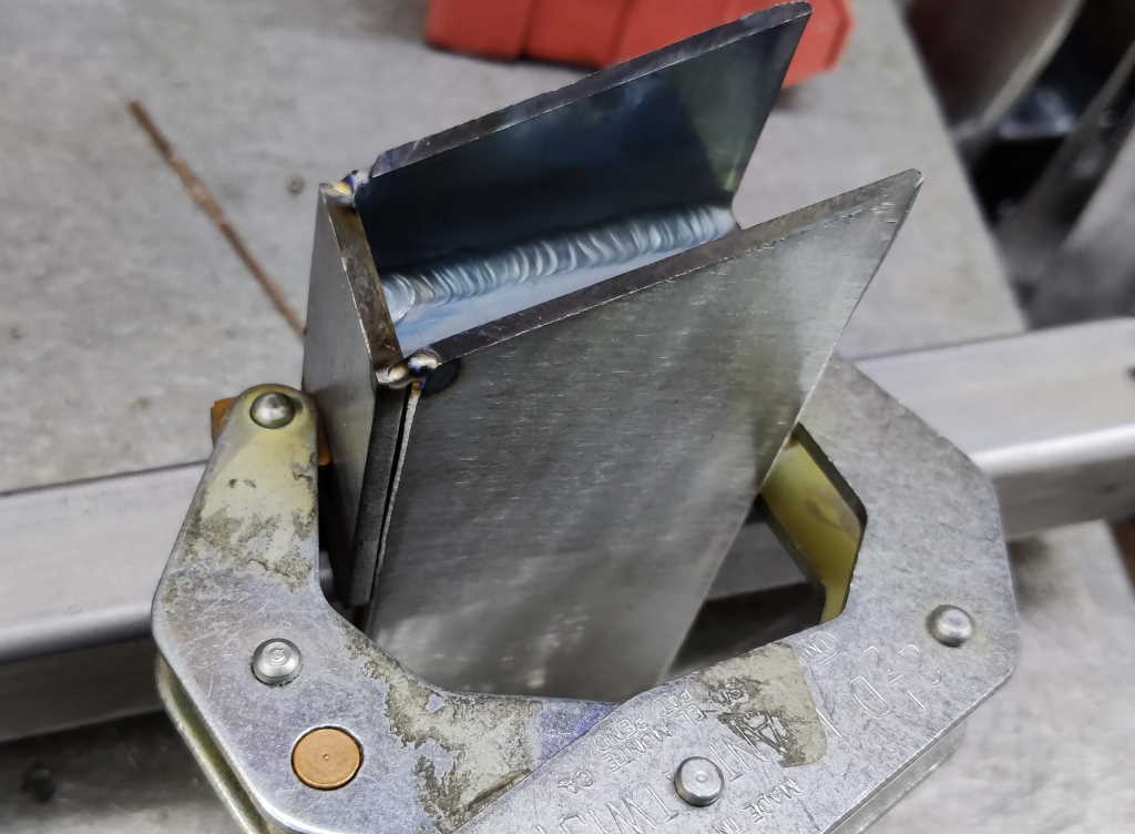
After putting two tacks at the top and one on the side not covered by the clamp, I took the clamp off, took the frame off the prototype bar and welded up each side.
One of the frames (the one that tilted backwards) had to be dealt with slightly differently. For this one I didn't use the feeler stock and, after lightly clamping the back in place, tapped the back down until the frame sat parallel with the bar. I then tacked and welded as before.
 |
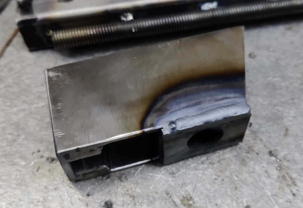
For the screw jaw the approach was very similar. The only differences were:
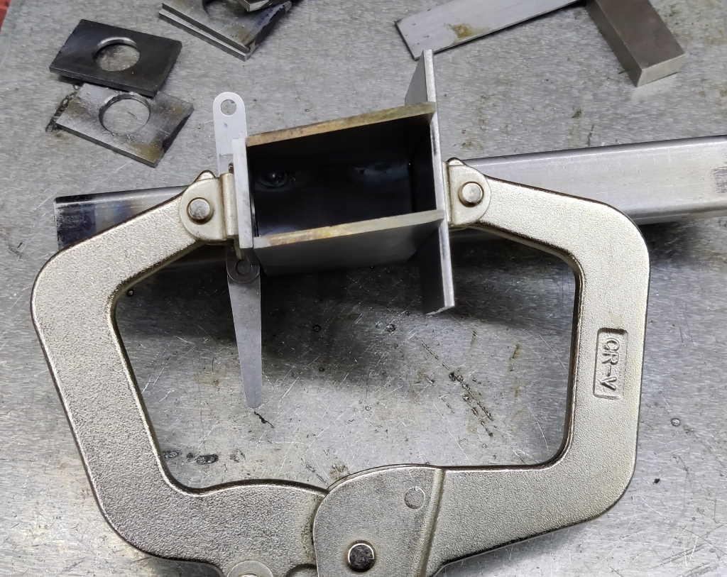
- With the sliding jaw, when in motion the back is lifted up and away from the bar. Therefore, the back piece can be safely placed very close to the bar. For the screw jaw, that's not the case so I used a thicker 1.5 mm spacer made up of two pieces of feeler gauge stock.
- The screw jaw doesn't have the box section all the way through, so I used a spare piece of steel on the front to give the clamp something to bear on.
You can see the clamping arrangement (with the C-clamp, which I used from the start on these jaws) in the photo above.
 |
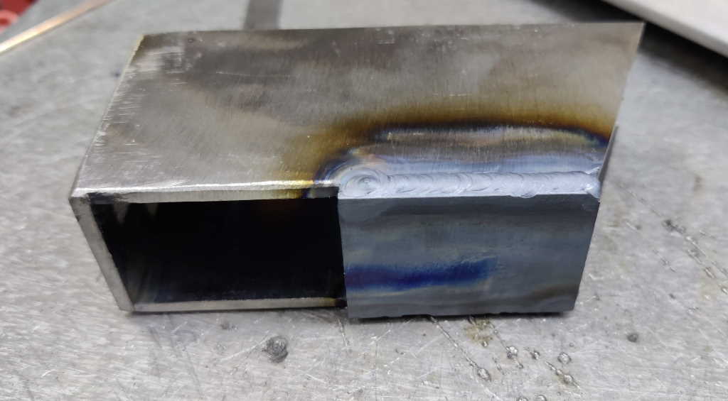
As with the sliding jaw, after removing the clamp and removing the frame from the prototype bar, I welded the back piece along both edges.
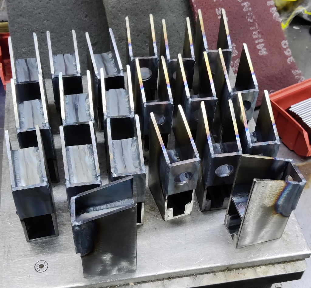 |
This photo shows all 20 frames ready to have their tops fitted.
Page Navigation:
| First (#1) | Previous (#15) | Next (#17) | Last (#32) |
This website is free, but costs me money to run. If you'd like to support this site, please consider making a small donation or sending me a message to let me know what you liked or found useful.