Kumiko Box Build Process
19/8/2022
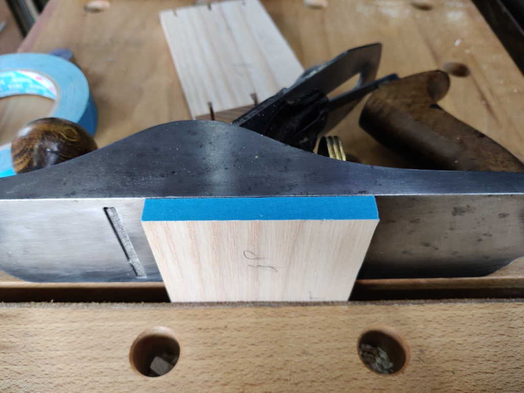
The first step in marking out the first pin board was to cover the end grain with some masking tape. I then put it in the vice of my portable workbench, raised up to match the width of my Stanley #4:
 |
I then took my 1 mm thick steel rule and clamped it to the tail board using a couple of offset jaw spring clamps. The end of the rule is slightly in-board of the reference edge and the side of the rule is flush with the knifed line on the inside face of the board:
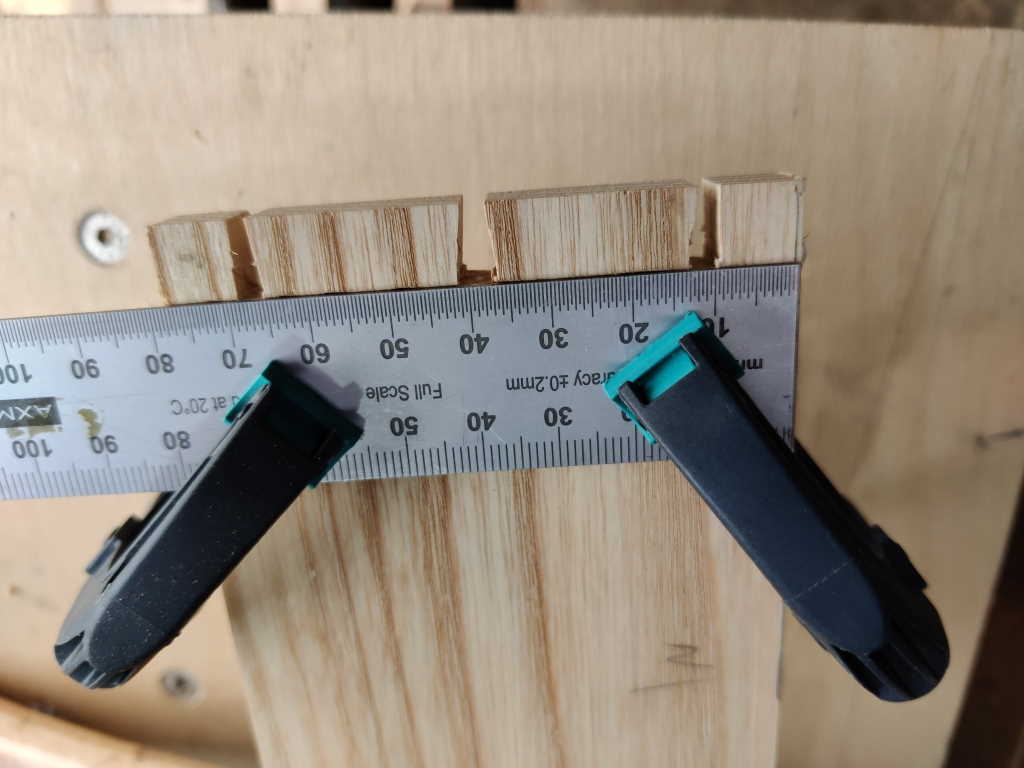 |
That 1 mm thick rule gives a "positive stop" for the tail board when offering it up to the pin board, making it really easy to get it into the right place. Having the ruler slightly in-board of the reference edge means I can use the back of a chisel to push the two reference edges into line, while relying on the ruler to keep the board at the right depth:
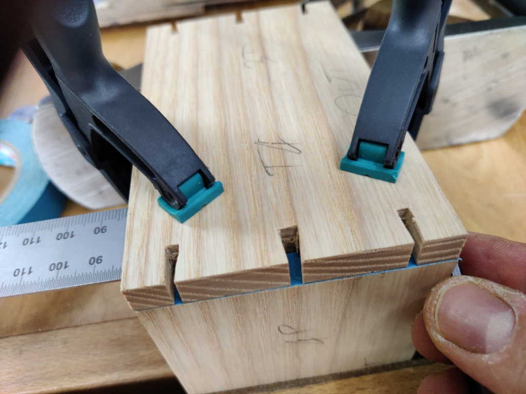 |
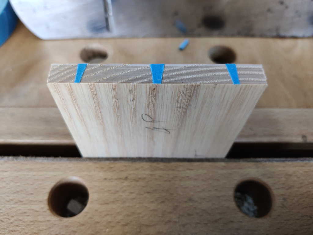
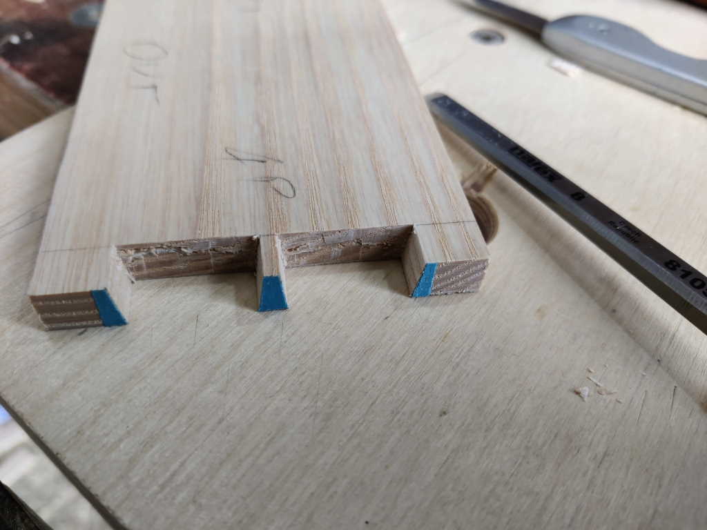
With the tail board held over the pin board, I use a knife to cut the masking tape in the pin sockets and can then peel the waste bits away:
 |
After running a pencil line across the outside face at about the right depth, I got the 1:8 jig out again and used its other sides to guide the saw through the pin cut. The saw guide is placed over the masking tape with the fence flush against the back of the board. The face is angled to match the angle produced when cutting the tails, so it simply needs to be slid up to the edge of the tape and it can then be used to guide the saw:
 |
This time I decided to go back to using the coping saw (no idea why really). Since it won't go down into the dozuki kerf, I tend to do the coping saw cuts in two passes. The first one starts at the top (a couple of millimetres away from the kerf) and angles down until it meets the other kerf:
 |
The second cut goes back across to clear the other side:
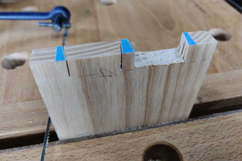 |
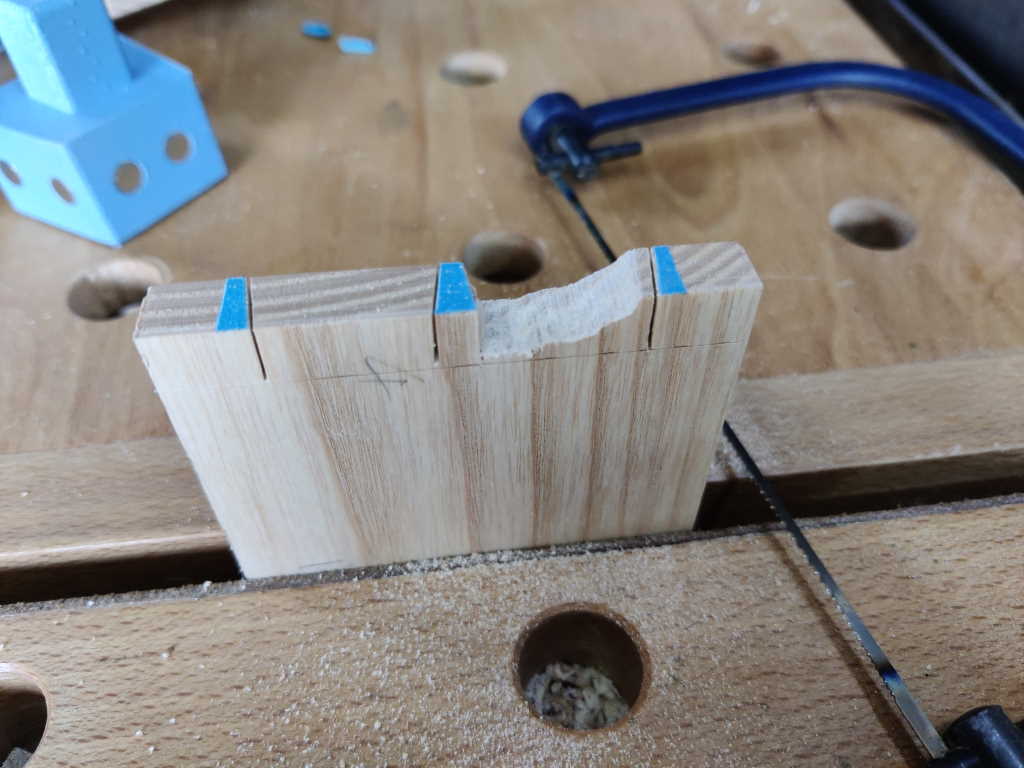
I can then chop out the rest of the waste (this time with an 8 mm chisel, although a bigger one would have worked fine):
 |
Next up was sawing off the mitres, keeping well away from the knifed line. First the tail board:
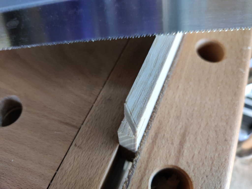 |
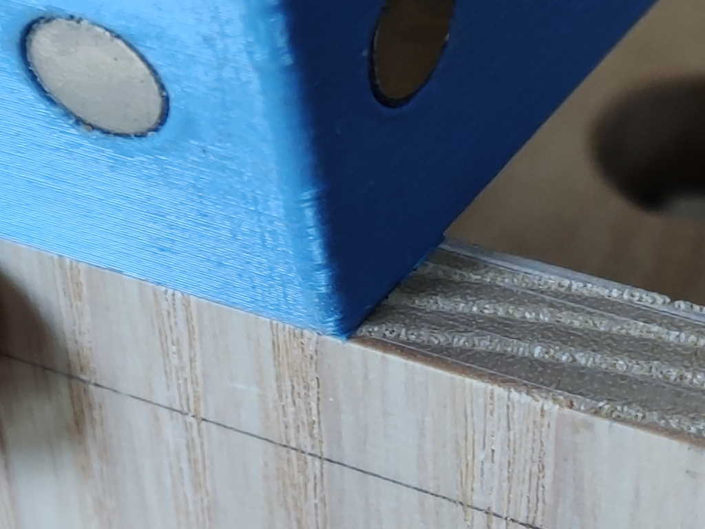
I then used another 90° 3D printed jig (with the saw handle held down low to make the 45° angle) to produce the two rip cuts:
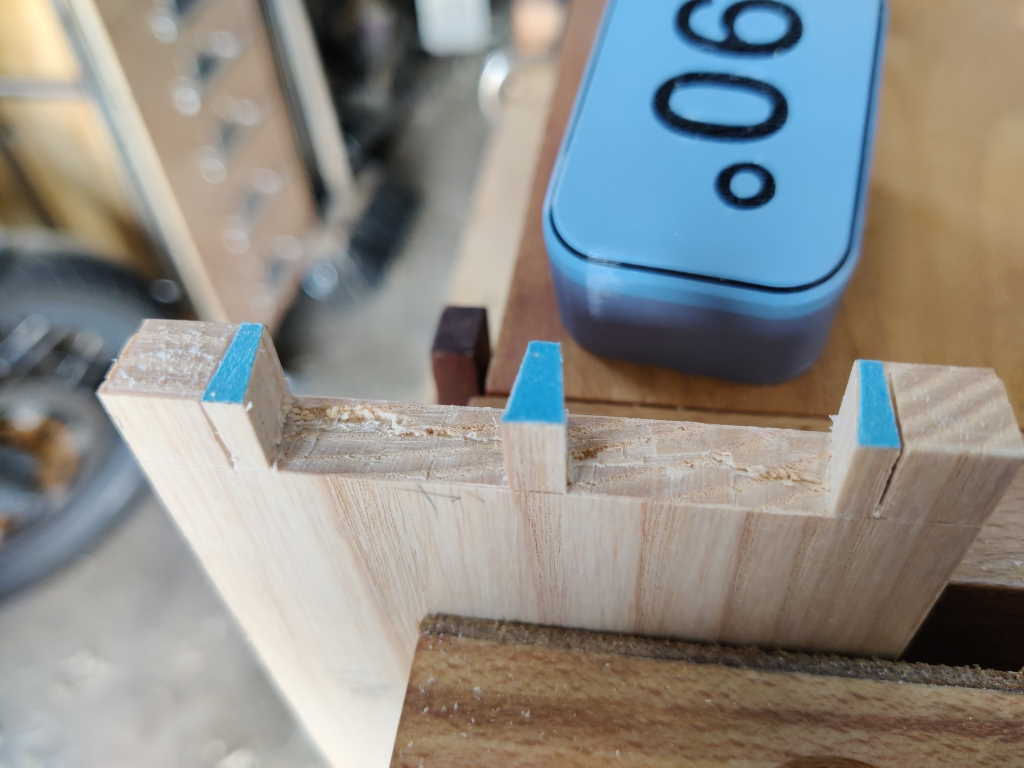 |
I could then saw off the waste, again staying away from the line:
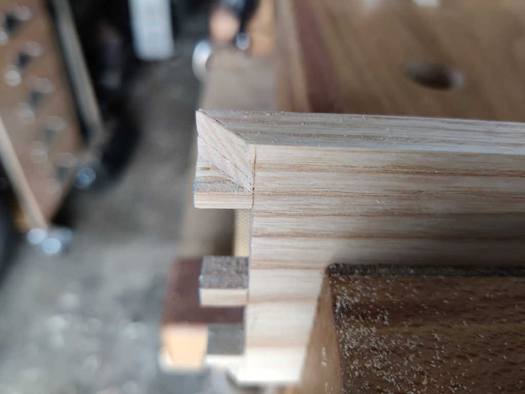 |
Page Navigation:
| First (#1) | Previous (#3) | Next (#5) | Last (#15) |
This website is free, but costs me money to run. If you'd like to support this site, please consider making a small donation or sending me a message to let me know what you liked or found useful.