Foot Switch for Lift-TIG Welding
 |  |
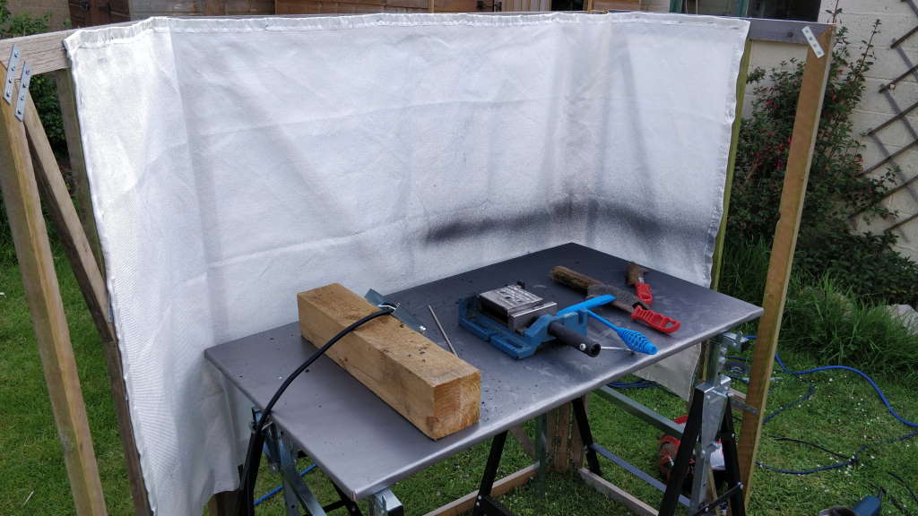
I have an Arc Welder, a Parweld XTS 163. It's a neat little machine and very light so is easy to move around when stick welding (which I tend to do outside, with a wooden framed curtain to stop the sparks / slag from going anywhere I don't want it to go).
The photo on the right above shows the set-up I use when stick welding. The welding table is a sheet of OSB that I've covered with a large sheet of mild steel. It sits on some heavy duty builder's trestles - I use these rather than the more common plastic ones as they can be extended to a much higher level than the plastic ones. I'm about 1.98 m (6'6") tall and this is one of the many, many extra things you have to think about when you're tall!
While the XTS 163 is designed as an arc welder, it includes some very basic TIG functionality, commonly referred to as Lift-TIG. This allows a valved TIG torch to be connected to the welder, the current set to a fixed value and the welder can then be used for TIG welding. This is a really nice feature on such a low-cost welder, but it suffers from a couple of problems:
- You can't dynamically control the current while you're welding to get a better weld pool.
- At the end of the weld you have to "flick" the torch away and then back again in order to stop welding: this tends to produce small craters in the end of the weld.
The first problem can only really be overcome by having a friend on hand to turn the control for you (although I've considered rigging a foot pedal up to a stepper motor linked to the control with an o-ring). The second problem can be overcome either by continuing the weld onto some sacrificial material (like a copper plate) or by breaking the circuit externally.
 |
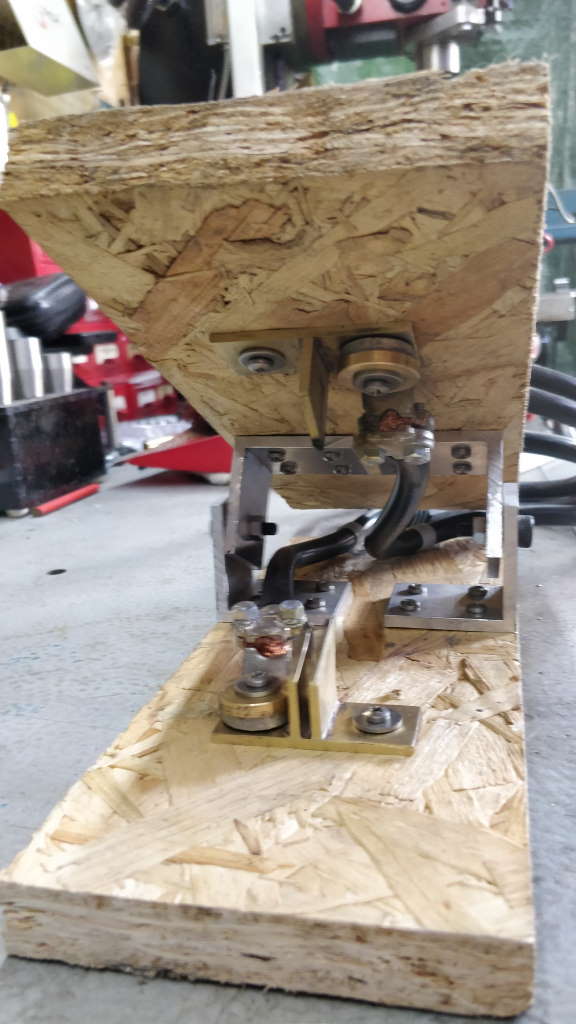
I went with the latter approach - building a custom switch that breaks the circuit to the return ("earth") clamp, thereby avoiding the damage to the part being welded. The photo above shows a side-on view of my custom foot pedal, which was made in a few hours to solve this problem.
 |  |
The photo on the left shows the top view of the foot pedal. As you can see, the connections to the foot pedal are via a long cable with a male 35-50 Dinse connector and via a short cable to a female 35-50 Dinse connector. The longer cable plugs into the positive terminal on the welder; the shorter cable connects to the existing return clamp cable that would otherwise have connected to the positive terminal. The torch is connected as usual.
The right-hand image shows a view into the front of the pedal. The perspective of the photo makes it looks warped, but that's just a mark of my poor photographic skills! With the exception of the Dinse connectors and the screw-terminal welding wire connections, the foot pedal was made entirely out of random bits of material I already had lying around, so you couldn't really describe it as carefully designed.
 |
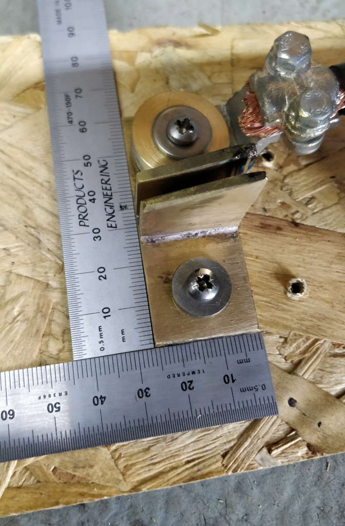
This photo shows a close up of the bottom part of the electrical switch. This was made out of 25 mm × 3 mm brass flat bar. The main bar (on both the top and bottom part of the switch) was cut to 60 mm long and some uprights were machined at an angle to match the angle that the foot pedal sits at when closed. The uprights were clamped between a spacer that was about 2.9 mm wide and silver soldered to the base piece. The top part of the switch was made in a similar way, but with only one upright. Once the two switch parts were made, they were adjusted with sandpaper until there was a tight fit between the mating parts. Holes were drilled for the mounting screws and a brass washer was made to fit the 4 mm wood screws into the 16 mm bore of the welding cable screw connector.
 |
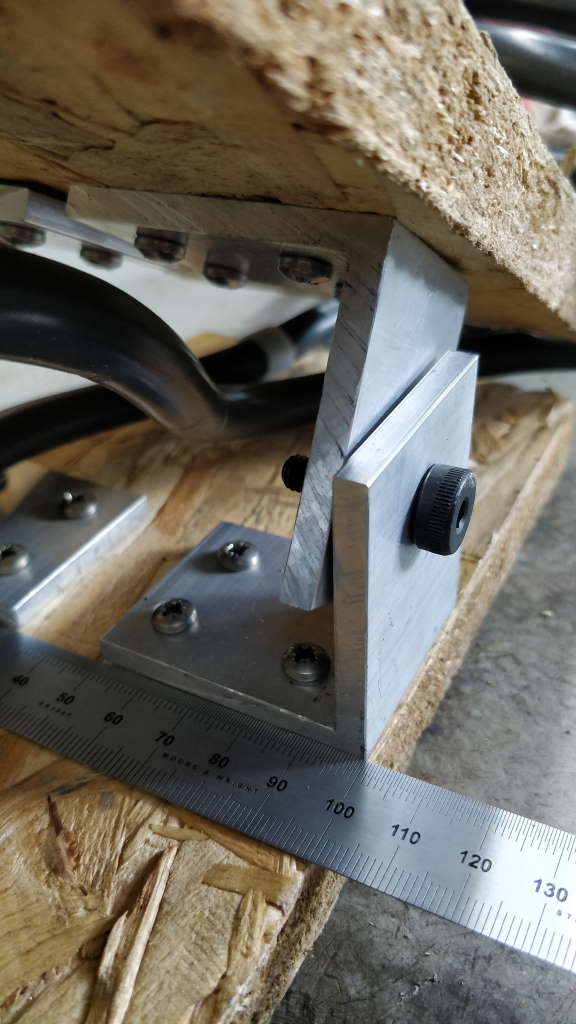
This photo shows a close-up of one of the hinges. This was rough cut to size with a bandsaw out of some 50 mm × 50 mm × 5 mm aluminium angle. The length (into the photo above) of each hinge section was about 40 mm - chosen purely as a result of having about 160 mm of aluminium angle. An 8 mm hole is drilled in the middle of the side, about 12 mm from the edge. Four 4 mm holes are drilled in the base for the mounting wood screws. Again simply because it was what came to hand, I used some M6 shoulder screws (which have an 8 mm shoulder) to connect them together. The shoulder length of the screws was slightly more than 10 mm; fixing a nut on the end of the shoulder screw allowed the hinge to turn freely.
In use, I close the foot pedal switch and then TIG weld normally. At the end of the weld I simply have to tilt my foot back to open the switch and the spark stops; after allowing some post-weld gas flow time, I can turn the valve off and the result is a much cleaner weld than without the foot pedal. In the photos above you can see the soot marks on the switch components from where the circuit has been broken, but this cleans off easily and most of the contact area is unaffected.
This website is free, but costs me money to run. If you'd like to support this site, please consider making a small donation or sending me a message to let me know what you liked or found useful.