Portable Workbench Build Process
8/3/2021
This project has been on my list for a while now, but I started the main body of work this weekend. The aim is to make a portable (ish) workbench that can be placed on top of my existing bench (or the dining table if necessary!) to give a raised work surface and a couple of different vices that can be used without being constrained to being in one fixed spot on my existing bench.
I've seen a few designs in various places; I might have got carried away with my design and also might have bitten off more than I can chew, but we'll see…
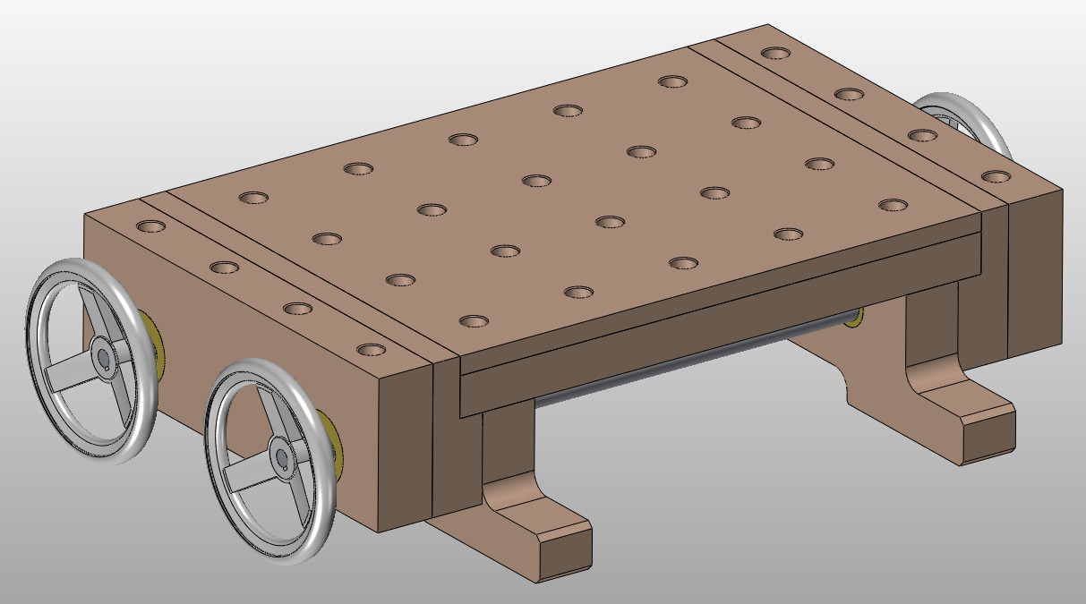 |
For a sense of scale, the total dimensions of the top surface (including the top of the vice jaws) will be 630 × 380 mm. The vice jaws are 50 mm thick. Including the feet (which stick out for ease of clamping down to another surface), the width is 530 mm. The total height is 166 mm. The dog holes are 20 mm diameter on a 96 mm pitch. The dog holes in the vice jaws will (like the ones on my existing bench) make for easy clamping of thin-ish stuff on the top.
The vice mechanisms will be based on M20 threaded rod; pretty much everything apart from the hand wheels and threaded rod will be made by me from the beech and some bits of brass & steel bar stock. I would have preferred to use M24 threaded rod, but I can get M20 threaded rod locally at a countryside store so I'm going with that for simplicity. I've also got some 30 mm OD, 5 mm wall thickness (and hence 20 mm ID) seamless mild steel tube and that's quite handy for the design given that I'm using 20 mm threaded rod.
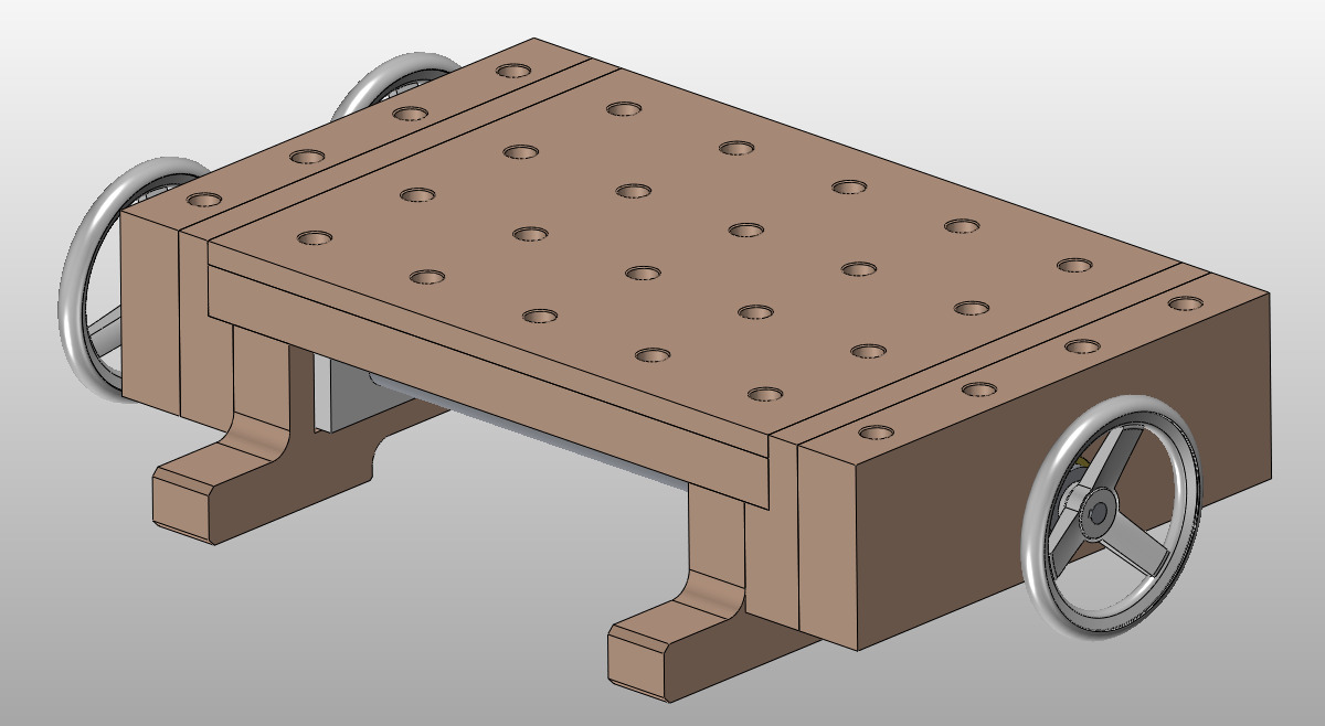 |
I should probably say at this stage that I'm not even going to try to do this as a hand tools project: this is intended to make it easier to do hand tool based woodworking projects, but I'm going to use every tool I've got to make this! I'm also not planning to include any fancy joinery: just whatever will work and be straightforward. It's going to be fairly hefty and several parts will have bits of brass or steel going through them so there's not much chance of things wandering off. I haven't decided how the rails will be attached to the fixed jaws yet (apart from that they'll go into a cut-out), but it'll probably either be just glue or glue & dowels. The top will be screwed in place (probably with slotted holes in the rails and buttons into slots in the feet) so that it can be removed if required.
I'm making this partly as I think it'll be really useful to have around, but also partly because I think I'll enjoy making it. There's lots of different aspects to this project: machine woodworking (lots of that), some hand tool woodworking, a fair amount of metal turning, a bit of metal milling and some TIG welding. I enjoy all of those things, so from my point of view it should be a good project, regardless of the outcome!
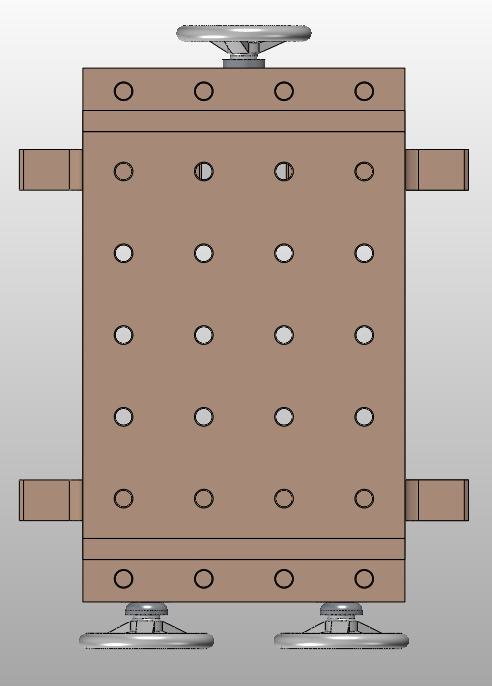 |
The plan is to have two vices (with home-made quick-release mechanisms). The one at the top of the image above is a conventional vice, with a central screw and two slider bars made of 30 mm OD, 20 mm ID steel tube. Being raised above my normal bench will be handy for cross-cutting stock as the hand saw will have somewhere to go at the bottom of the cut. I'm wondering about adding a dowel into the right-hand side of the fixed jaw of the conventional vice (top-left of the image above) so if I'm a bit over eager with the hand saw at the end of the cut it'll hit the dowel rather than the workbench underneath - the dowel would be easily swapped out once it gets beaten up.
The vice at the bottom of the picture is a dual-screw "Moxon-style" vice with slots in the moving jaw to allow angled clamping. Assuming it works, this should allow me to clamp long workpieces vertically in the vice - up to 200 mm wide. It'll also cope with tapered workpieces thanks to the slotted bushes in the moving jaw.
This picture shows what it would look like with the jaws open:
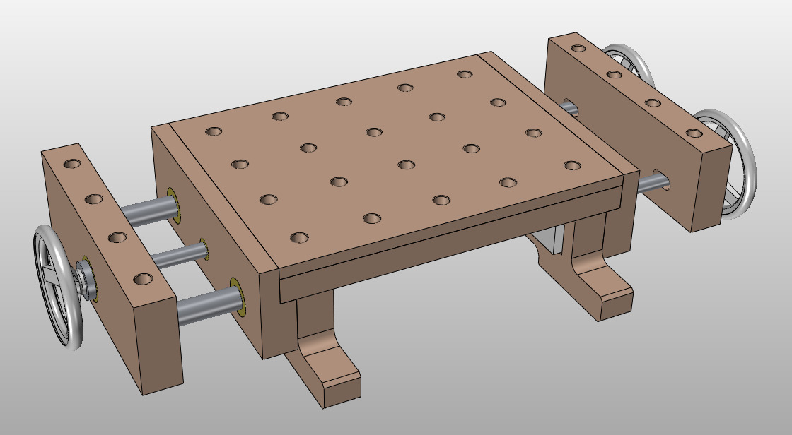 |
This is a view of it with the top surface hidden: note that I've modelled the vice mechanisms as simple white boxes for now; I might update the model once I've made them and know the actual details a bit more accurately.
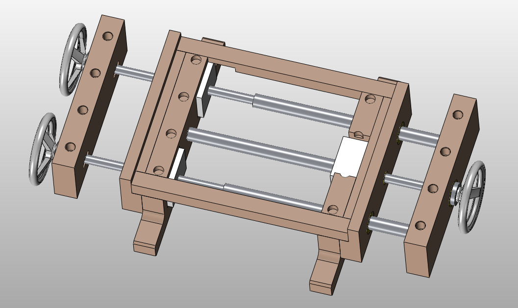 |
Here are a couple of views of the angled vice jaw (at somewhere near the maximum angle that will be possible with the slots as drawn):
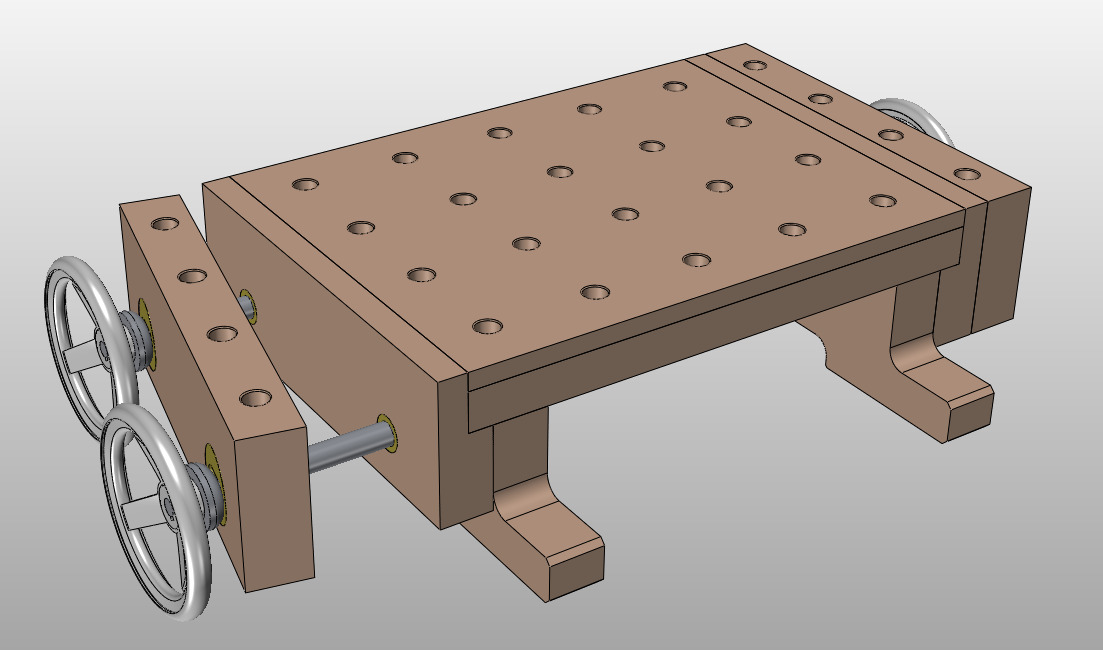 |
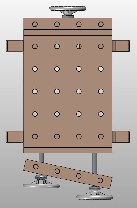 |
The source material is a 4 metre-ish long piece of beech that was about 150 mm × 50 mm or thereabouts in section (I didn't measure it before cutting it up, but some of the shortened lengths ended up 50 mm thick after planing, so it must have been a bit over that to start with). I cut it up into lengths, planed it (router sled for one side, thicknesser for the other) and measured all the bits that were left. I then updated the CAD model to suit!
I'd planned the top surface of the workbench to be 18 mm thick. I planed the four individual pieces to 18 mm thick, then edge jointed them. I didn't get that quite right and ended up taking another 2 mm off the thickness to get them flat and of a consistent thickness, so the top is now 16 mm thick. I think that should be fine though, the unsupported width (between the two side rails) is only 310 mm.
Page Navigation:
| First (#1) | Next (#3) | Last (#67) |
This website is free, but costs me money to run. If you'd like to support this site, please consider making a small donation or sending me a message to let me know what you liked or found useful.